
Light-negative moulding set

A backlight module and light source technology, applied in optics, nonlinear optics, instruments, etc., can solve the problems affecting the display brightness and quality of the display panel, increasing the structural complexity of the backlight module, and the actual production difficulty of the light guide plate. The effect of light energy utilization, elimination of dark bands, and simplification of structure

Inactive Publication Date: 2007-01-17
HONG FU JIN PRECISION IND (SHENZHEN) CO LTD +1
View PDF0 Cites 6 Cited by
  • Summary
  • Abstract
  • Description
  • Claims
  • Application Information

AI Technical Summary

Problems solved by technology

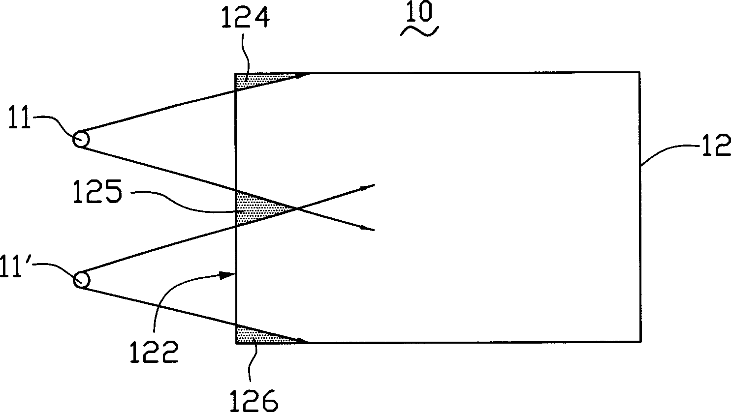
Therefore, in the backlight module 10, when the light sources 11, 11' are incident on the light guide plate 12, there will be dark bands 124, 125 and 126 in the light guide plate 12, and since the entire light guide plate 12 is usually connected with the main body of a display panel The display area corresponds, so the dark band areas 124, 125 and 126 seriously affect the display brightness and quality of the display panel
[0005] In order to eliminate dark bands, a certain microstructure is usually formed on the light-incident surface or the light-exit surface in order to eliminate dark bands. However, in these methods, when the light source is incident on the light-incident surface, there are still dark bands. These microstructures can only reduce but cannot completely eliminate the generation of dark bands, and special design of these microstructures is required in the manufacture of light guide plates. These microstructures are formed by molds or other processes, which brings great difficulties to the actual production of light guide plates that require these microstructures, and increases the structural complexity of the entire backlight module.

Method used


Image

  • Light-negative moulding set
  • Light-negative moulding set
  • Light-negative moulding set

Examples


Embodiment Construction

[0026] The technical solution will be described in further detail below in conjunction with the accompanying drawings.

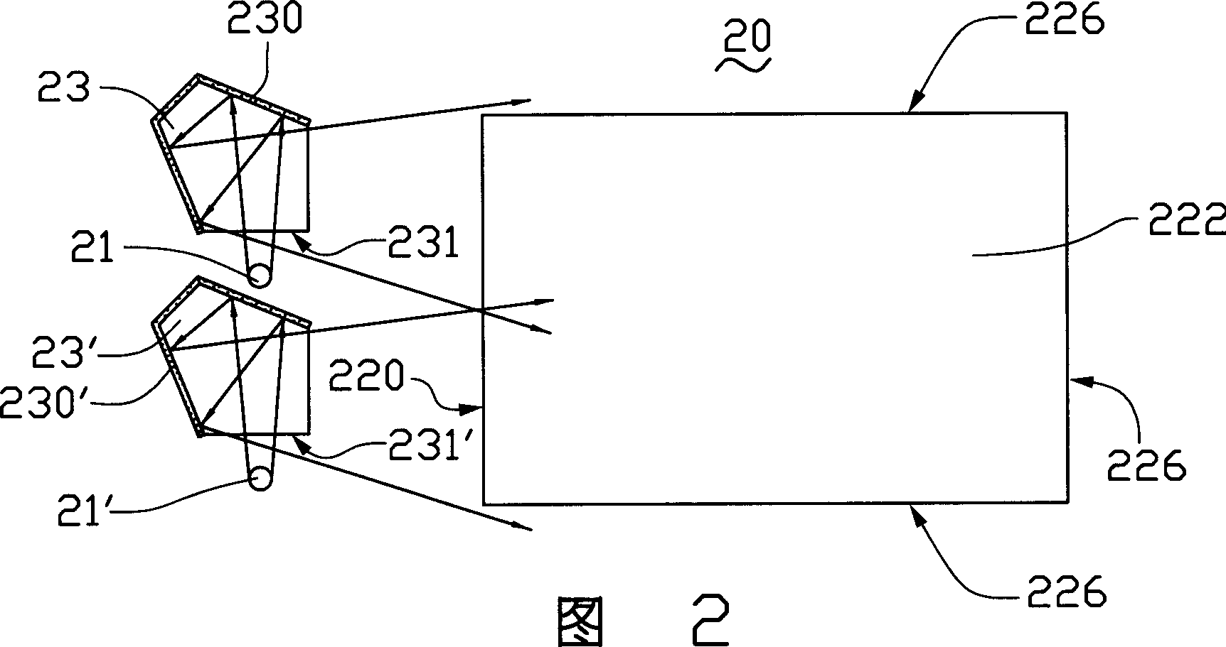
[0027] Please refer to Figure 2 and image 3 , is a schematic structural diagram of the backlight module provided in this embodiment. The backlight module 20 includes two light sources 21, 21', a light guide plate 22 and two multiple reflection devices corresponding to the light sources 21, 21'. Wherein, the multiple reflection device adopts pentagonal prisms 23, 23', and the two pentagonal prisms 23, 23' are located in the light path from the light beams emitted by the two light sources 21, 21' to the light guide plate 22.

[0028] Generally, the light source 21, 21' can be a point light source or a line light source, such as a fluorescent tube, a cold cathode lamp or a light emitting diode, etc. In this embodiment, two light emitting diodes are used as the two point light sources 21, 21'.

[0029] The light sources 21, 21' can be located on the same side...


PUM


Abstract

This invention supplies a back light module, which at least concludes one illuminant and one light guide plate. This light guide plate has a light-entry surface and a light-outward surface that next to the light-entry surface. This back light module also concludes at least a multireflection device that can make light beam emitted by the illuminant couple to beam path of light-entry surface. Through this reflection device, the angle of departure of illuminant is enlarged. This can slake the dark band that is generated when light enter into light guide plate. This can increase luminance of the back light module and make the structure simplify.

Description

【Technical field】 [0001] The invention relates to a backlight module. 【Background technique】 [0002] In recent years, flat panel display devices have developed rapidly and have been widely used in fields such as personal computers, televisions, mobile communications, and consumer electronics products, becoming a major platform for information technology. At the same time, the requirements of electronic products for backlight modules in flat-panel display devices (such as liquid crystal display devices) continue to increase, and high brightness, lightness, low cost, low energy consumption, and long life have become the development direction of backlight modules. [0003] According to the position of the light source, the backlight module can be divided into direct type and side type. The direct type refers to placing the light source directly under the light guide plate to directly illuminate the light guide plate. The disadvantage of this type of backlight module is that ...

Claims


Application Information

Patent Timeline
IPC IPC(8): G02F1/1335
Inventor 邱文赐
Owner HONG FU JIN PRECISION IND (SHENZHEN) CO LTD
Learn More