
Package substrate

A technology for packaging substrates and substrates, which is used in the manufacture of multilayer circuits, electrical connection of printed components, printed circuit components, etc.

Inactive Publication Date: 2007-01-17
IBIDEN CO LTD
View PDF1 Cites 0 Cited by
  • Summary
  • Abstract
  • Description
  • Claims
  • Application Information

AI Technical Summary

Problems solved by technology

That is, if Figure 24 (C) shown Figure 23 As shown in the enlarged view of the through hole 660D and the solder bump 675 in , the wiring 678 connecting the solder bump 675D on which the solder bump 676D is placed and the through hole 660D is disconnected due to the presence of the crack L2.

Method used


Image

  • Package substrate
  • Package substrate
  • Package substrate

Examples


Embodiment Construction

[0046] (first embodiment)

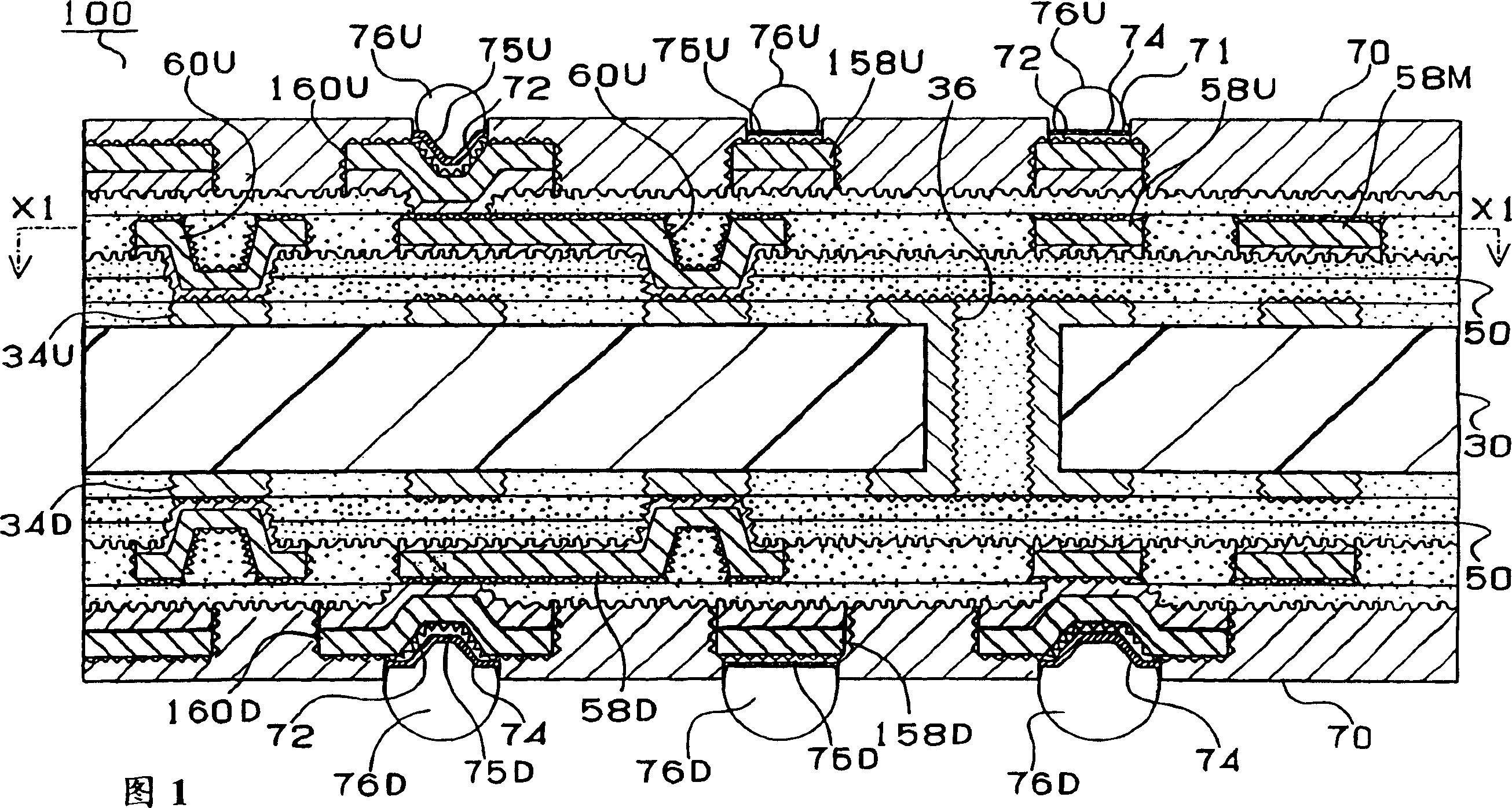
[0047] The configuration of a package substrate according to a first embodiment of the present invention will be described with reference to FIG. 1 . 1 shows a cross-sectional shape of a package substrate according to a first embodiment. This package substrate constitutes a so-called integrated circuit package and is used to mount an integrated circuit (not shown) on a motherboard (not shown) in a state where it is placed thereon. )superior. The package substrate is provided with soldering bumps 76U for connecting to the soldering bump side of the integrated circuit on the upper side, and soldering bumps 76D for connecting with the soldering bumps of the motherboard on the lower side. The boards play the role of transmitting signals, etc. and relaying the power supply from the motherboard.

[0048] Inner layer copper patterns 34U, 34D as ground layers are formed on the upper and lower surfaces of the chip substrate 30 of the package substrate. In...


PUM


Abstract

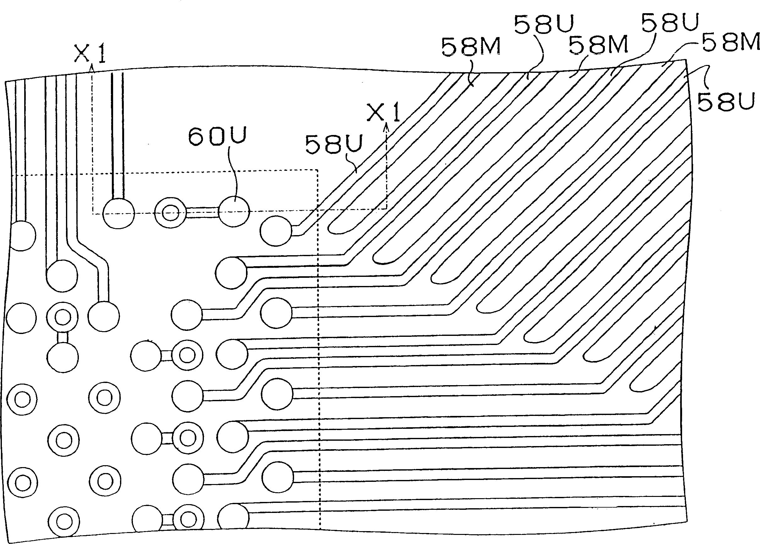
According to the package board of the present invention, each soldering pad formed on the top surface of the package board, on which an IC chip is to be mounted, is small (133 to 170 mum in diameter), so the metallic portion occupied by the soldering pads on the surface of the package board is also small. On the other hand, each soldering pad formed on the bottom surface of the package board, on which a mother board, etc. are to be mounted, is large (600 mum in diameter), so the metallic portion occupied by the soldering pads on the surface of the package board is also large. Consequently, a dummy pattern 58M is formed between conductor circuits 58U and 58U for forming signal lines on the IC chip side surface of the package board thereby to increase the metallic portion on the surface and adjust the rate of the metallic portion between the IC chip side and the mother board side of the package board, protecting the package board from warping in the manufacturing processes, as well as during operation.

Description

[0001] This application is a divisional application of an invention patent application with the application number 200410045619.0, the filing date is September 28, 1998, the divisional submission date is May 10, 2004, and the invention title is "package substrate". technical field [0002] The present invention relates to a package substrate for mounting an IC chip. More specifically, the present invention relates to a pad for connecting an IC chip and a substrate for connecting a motherboard, a daughter board, etc., formed on the upper surface and the lower surface, respectively. the solder pads of the package substrate. Background technique [0003] Highly integrated IC chips are loaded on the packaging substrate and connected to the motherboard, daughter board and other substrates. Figure 23 A state in which the IC chip 80 is loaded on the package substrate 600 and mounted on the motherboard 90 is shown, refer to Figure 23 The configuration of this package substrate will...

Claims


Application Information

Patent Timeline
IPC IPC(8): H01L23/498H01L23/12H05K1/02H05K1/11H05K3/46
CPCH01L2224/16225H01L2224/32225H01L2224/73204
Inventor 浅井元雄森要二
Owner IBIDEN CO LTD
Learn More