Engine output control device
A technology of engine output and control device, applied in the direction of engine control, machine/engine, electrical control, etc., can solve problems such as starting acceleration dissatisfaction, vehicle speed difference, etc., and achieve the effect of eliminating the deterioration of acceleration performance
Active Publication Date: 2007-01-24
NISSAN MOTOR CO LTD
0 Cites 9 Cited by
AI-Extracted Technical Summary
Problems solved by technology
[0015] Therefore, when the driver is accelerating from a start, when the speed change start speed VSP1 is greater than or equal to, the driver feels that the acceleration performance deteriora...
Method used
[0104] Therefore, after the shift start instant t2, the lack of driving force in the shift from the lowest gear ratio can be realized by increasing the engine output torque Te and the engine speed Ne along...
Abstract
The invention prevents the deterioration in an increase in acceleration when driving force reduces by a shift start from the lowest when starting with accelerator opening held constant. When a vehicle speed VSP is less than a shift starting vehicle speed VSP1 to start a shift from the lowest different every accelerator opening APO, target throttle opening tTVO is determined as reference opening corresponding to a map for a low vehicle speed, and afterwards, the target throttle opening tTVO is gradually increased to opening with every accelerator opening APO corresponding to a map for a high vehicle speed for increasing the vehicle speed VSP. Thus, the deterioration in acceleration performance can be prevented after starting the shift by increasing engine output torque by an increase in the target throttle opening tTVO in response to time when becoming the vehicle speed VSP1 for starting the shift from the lowest gear ratio, and this action effect can be realized without changing the driving force at the shift starting vehicle speed VSP1.
Application Domain
Electrical controlMachines/engines +1
Technology Topic
Gear ratioAcceleration Unit +1
Image
Examples
- Experimental program(1)
Example Embodiment
[0057] Hereinafter, the embodiments of the present invention will be described in detail based on the embodiments shown in the drawings.
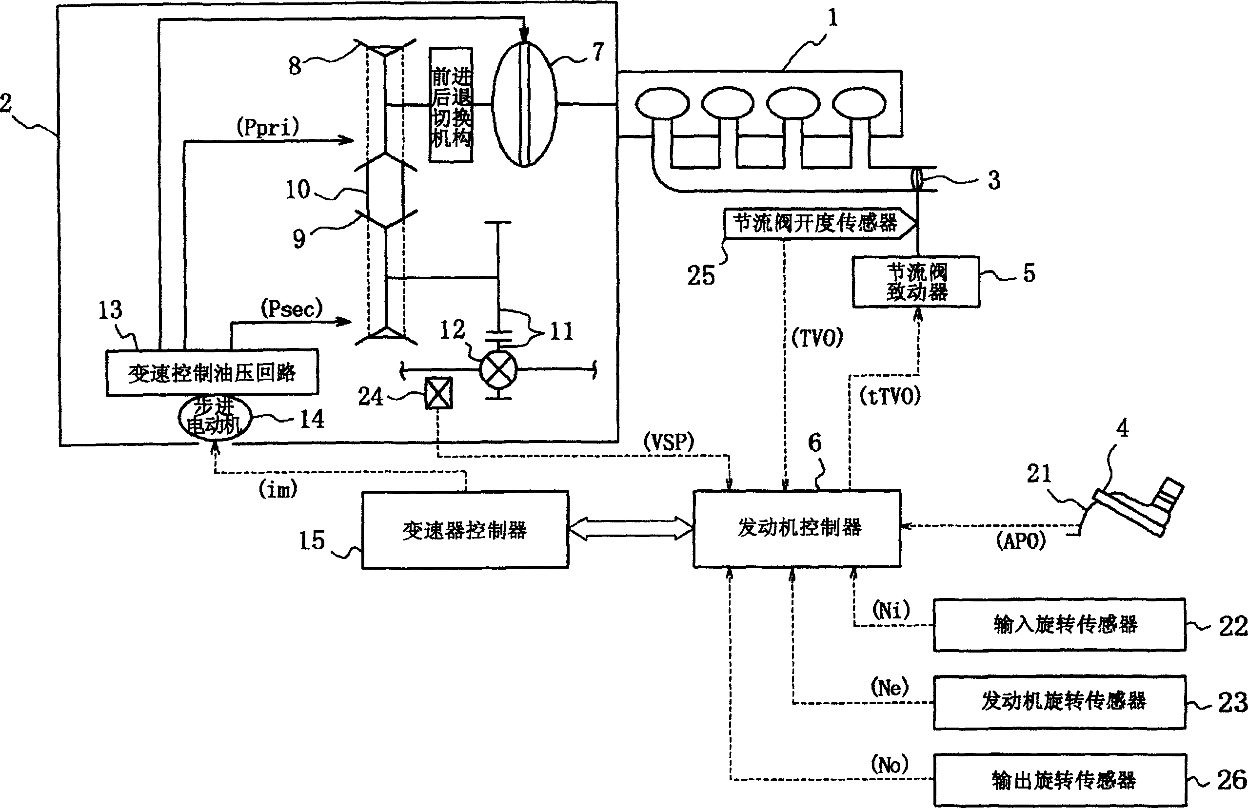
[0058] figure 1 A vehicle power transmission system and a control system thereof having an engine output control device according to an embodiment of the present invention are shown, and the power transmission system is composed of an engine 1 and a continuously variable transmission 2.
[0059] The engine 1 is a gasoline engine, but the throttle valve 3 as its output determination unit is not mechanically connected to the accelerator pedal 4 operated by the driver, but is separated from it, and the throttle valve 3 is adjusted by the throttle valve actuator 5 The opening degree is electronically controlled.
[0060] The throttle valve actuator 5 operates in accordance with the target throttle valve opening degree tTVO, and is controlled by the amount of action, the target throttle valve opening degree tTVO being determined by the engine controller 6 according to the operation of the accelerator pedal 4 as described later Therefore, the opening degree of the throttle valve 3 can be controlled to coincide with the target throttle valve opening degree tTVO, so that the output of the engine 1 becomes a value substantially corresponding to the operation of the accelerator pedal 4. Control factors other than accelerator pedal operation.
[0061] In addition, the engine controller 6 does not only use the throttle valve actuator 5 to perform the above-mentioned throttle valve opening degree control. Although not shown, in addition to this, it also performs the fuel injection amount control required when the engine 1 is running. , Oil cut control, ignition timing control or valve lift control of intake and exhaust valves.
[0062] Because these fuel injection quantity control, fuel cut-off control, ignition timing control, or valve lift control of the intake and exhaust valves also determine the engine output, the engine output determination unit is not limited to the above-mentioned throttle valve 3, and obviously can also be implemented. These controlled devices.
[0063] The continuously variable transmission 2 uses a well-known V-belt type continuously variable transmission, which has: a main pulley 8 which is drivingly engaged with the output shaft of the engine 1 via a torque converter 7; an auxiliary pulley 9 which is aligned with the main pulley 8; And the V-belt 10, which is erected between the two pulleys.
[0064] In addition, the auxiliary pulley 9 drives and engages the differential gear device 12 via the final reduction drive gear set 11, and with such a structure, the left and right drive wheels (not shown) are rotationally driven.
[0065] The shifting action of the continuously variable transmission 2 is carried out in such a way that, of the flanges forming the V-groove of the main pulley 8 and the auxiliary pulley 9 respectively, the movable flange on one side is fixed relative to the other side. The flanges are close to narrow the width of the V-groove, or conversely separate it to enlarge the width of the V-groove. The ratio of the main pulley pressure Ppri and the auxiliary pulley pressure Psec from the transmission control hydraulic circuit 13 is used to compare the two The stroke position of the movable flange is determined.
[0066] The variable speed control hydraulic circuit 13 has a stepping motor 14 as a variable speed actuator, and the transmission controller 15 drives it to a step position corresponding to the target speed ratio im, thereby causing the continuously variable transmission 2 to be continuously variable The actual gear ratio coincides with the target gear ratio im.
[0067] The engine controller 6 and the transmission controller 15 not only perform the control of the engine 1 and the continuously variable transmission 2 described above, but also communicate input information and calculation results with each other to coordinate the control of the engine 1 and the continuously variable transmission 2 .
[0068] To this end, the following various signals are input to the engine controller 6: as input information common to the two controllers 6, 15 from an accelerator opening sensor that detects the amount of depression of the accelerator pedal 4 (accelerator opening) APO 21; the signal from the input rotation sensor 22 that detects the input rotation speed Ni of the continuously variable transmission 2; the signal from the engine rotation sensor 23 that detects the engine rotation speed Ne; the signal from the vehicle speed sensor 24 that detects the vehicle speed VSP Signal; a signal from the throttle opening sensor 25 that detects the throttle opening TVO of the throttle valve 3; and a signal from the output rotation sensor 26 that detects the output rotation speed No of the continuously variable transmission 2.
[0069] Transmission controller 15 in accordance with Picture 12 with Figure 14 The target gear ratio im is determined in the above-mentioned manner, and thus, by driving the stepping motor 14 to a step position corresponding to the target gear ratio im, the continuously variable transmission 2 is continuously variable to the actual gear ratio i=Ni/No and The target gear ratio im=tNi/No coincides.
[0070] To achieve the purpose of the present invention, the engine controller 6 executes figure 2 The processing shown in the block diagram of, determines the target throttle opening tTVO.
[0071] The low vehicle speed target throttle opening degree calculation unit 31 obtains the low from the accelerator opening degree APO based on the low vehicle speed target throttle opening degree tTVO(Low) change characteristic map LowMap corresponding to the accelerator opening degree APO The vehicle speed uses the target throttle opening TVO(Low).
[0072] The high vehicle speed target throttle opening degree calculation unit 32 obtains the high from the accelerator opening degree APO based on the high vehicle speed target throttle opening degree tTVO(High) change characteristic map HighMap corresponding to the accelerator opening degree APO Vehicle speed target throttle opening TVO (High).
[0073]The transition coefficient calculation unit 33 obtains a transition coefficient Kp for determining the transition pattern from the low-vehicle speed map LowMap to the high-vehicle speed map HighMap.
[0074] The transition coefficient calculation unit 33 is provided with a predetermined transition coefficient map for determining the change characteristic of the transition coefficient Kp corresponding to the vehicle speed VSP. The change characteristic of the transition coefficient Kp is maintained when the vehicle speed is lower than the transition start vehicle speed VSP1 at which the transition coefficient Kp=0. Kp=0, when the vehicle speed is higher than the transition coefficient Kp=1, the transition end vehicle speed VSP2 maintains Kp=1. Within the vehicle speed range of VSP1 to VSP2, the transition coefficient Kp gradually increases from 0 to 1 as the vehicle speed VSP increases.
[0075] In addition, the change characteristic of the transition coefficient Kp is different for each accelerator opening degree APO, and changes in such a way that as the accelerator opening degree APO increases, starting from the characteristic indicated by the solid line, as shown by the one-dot chain line, the transition coefficient The transition start vehicle speed VSP1 at Kp=0 decreases, and the transition end vehicle speed VSP2 increases at the transition coefficient KP=1.
[0076] The transition coefficient calculation unit 33 searches and obtains the transition coefficient Kp from the low-vehicle speed map LowMap to the high-vehicle speed map HighMap from the accelerator opening degree APO and the vehicle speed VSP based on the change map of the transition coefficient Kp described above.
[0077] The high vehicle speed throttle opening TVO (High) is given a weight that directly uses the transition coefficient Kp corresponding to the vehicle speed VSP, and becomes Kp×TVO (High), and the low vehicle speed target throttle opening TVO (Low) is assigned Assign the weight obtained from (1-Kp) to (1-Kp)×TVO(Low), and the sum of the weighted target throttle opening degree, namely Kp×TVO(High)+(1- Kp)×TVO(Low) is used as the final target throttle opening tTVO.
[0078] Thus, as image 3 As shown, the vehicle speed VSP is less than the transition start vehicle speed VSP1, which is different for each accelerator opening degree APO, and the target throttle opening tTVO is determined according to the low vehicle speed map LowMap. If the vehicle speed VSP is greater than or equal to each accelerator opening degree When the transition end vehicle speed VSP2 differs from APO, the target throttle opening tTVO is determined based on the high vehicle speed map HighMap. As the vehicle speed VSP rises from VSP1 to VSP2, the low vehicle speed map LowMap corresponds to the high vehicle speed. Figure HighMap performs interpolation while determining the target throttle opening tTVO in a gradually increasing manner.
[0079] In addition, the low vehicle speed uses the corresponding map LowMap such as figure 2 As shown, the target throttle opening tTVO changes linearly with respect to the accelerator opening APO, and is smaller than the target throttle opening tTVO at the transition start vehicle speed VSP1, and becomes the reference throttle opening corresponding to the low vehicle speed characteristics. .
[0080] Therefore, as the vehicle speed VSP increases from VSP1 to VSP2, the target throttle valve opening degree tTVO gradually increases from the reference throttle valve opening degree to the target throttle valve opening degree corresponding to the high vehicle speed map HighMap.
[0081] In this embodiment, as described above, image 3 Illustratively determine the target throttle valve opening tTVO, as a command figure 1 figure 2 Send to engine 1 in the manner shown.
[0082] Thus, the engine 1 passes through the throttle valve actuator 5 (refer to figure 1 ) To make the actual throttle valve opening degree TVO coincide with the target throttle valve opening degree tTVO, and generate from the opening degree, engine speed Ne, figure 2 The engine output torque Te determined by the exemplary engine output characteristics.
[0083] According to the engine output control device of the present embodiment with the above structure, since it corresponds to the increase in the vehicle speed VSP in addition to the accelerator opening degree APO, the operation amount (throttle valve 3) of the engine output determining unit is increased. Valve opening (TVO) to image 3 The way of instantiation is increased, so it can be eliminated based on Figure 14 The aforementioned problem is that the driving force of the vehicle is reduced and the acceleration performance is deteriorated due to the upshift of the continuously variable transmission 2 whose gear ratio i is lowered when the gear ratio i is higher than or equal to the vehicle speed VSP1 at the start of the shift.
[0084] In addition, as described in this embodiment, in the case of controlling the throttle opening TVO corresponding to the vehicle speed VSP in addition to the accelerator opening degree APO, the target throttle is set corresponding to the accelerator opening degree APO and the vehicle speed VSP. The change characteristics of the throttle opening tTVO, that is, the change of the target throttle opening tTVO with respect to the change of the accelerator opening APO and the change of the vehicle speed VSP are relaxed. With this setting, it is not difficult to eliminate the change based on Fig. 16 The above-mentioned problem in (a) is the impact caused by the sudden change in the rate of change when the actual driving force does not reach the target driving force tF, and the above-mentioned problem based on Figure 16(b), that is, the change in the target engine torque tTe problem.
[0085] Figure 4 Shows another embodiment of the present invention. In this embodiment, the transition from the low vehicle speed map LowMap to the high vehicle speed map HighMap starts the vehicle speed VSP1, that is, the target throttle opening tTVO is changed from the low vehicle speed The vehicle speed VSP1 at which the reference throttle opening degree corresponding to the map LowMap starts to increase is determined as follows for each accelerator opening degree APO.
[0086] That is, and based on Picture 12 with Figure 14 In the same manner as described above, the transmission controller 15 sets the transition start vehicle speed VSP1 and the shift start vehicle speed VSP1 from the lowest speed ratio on the shift map used when determining the target input speed tNi for each accelerator opening degree APO (although Figure 14 Shows the vehicle speed at a certain accelerator opening APO, but as Figure 4 As shown, the APO is different for each accelerator opening).
[0087] According to the structure of this embodiment, based on Figure 14 To explain, that is, taking the vehicle speed VSP1 at which the gear shift starts from the lowest gear ratio as the timing, the target throttle opening tTVO increases and the engine output torque Te increases, and the decrease in the driving force at the start of the shift is the timing increase. The large engine output torque Te can smoothly solve the problems related to the deterioration of acceleration performance without being accompanied by changes in driving force.
[0088] The purpose of each of the above-mentioned embodiments is to solve the problem related to insufficient driving force after the start of the shift during acceleration at the start, but just after the start, such as Figure 5 As shown by the dotted line in the middle, due to the torque increase effect generated by the slip of the torque converter, there is a concern that a sudden sense of vehicle acceleration G will occur.
[0089] The problem can be as Figure 6 As shown, immediately after the start, the target throttle opening tTVO is made smaller than the reference throttle opening corresponding to the low-vehicle speed characteristics, so as Figure 5 As shown by the middle solid line, the peak of the vehicle acceleration G is suppressed.
[0090] The small target throttle opening tTVO just after the start is to ensure the continuity of the throttle opening TVO, so it needs to be carried out in a way that gradually increases toward the reference throttle opening as the vehicle speed VSP increases. determine.
[0091] However, at this time, such as Figure 7 As shown, if for each accelerator opening degree APO, the target throttle opening degree tTVO reaches the reference throttle opening degree when the reference opening degree reaches the vehicle speed, and based on Figure 4 The transition start speed (shift start speed) VSP1 determined by the above method is inconsistent, then such as Figure 8 As shown, in the vehicle speed range between the reference opening degree reaching the vehicle speed and the transition start vehicle speed (shift start vehicle speed) VSP1, the target throttle opening degree tTVO is maintained as the reference throttle opening degree.
[0092] In this case, in Picture 9 During the period indicated by t1 to t2, the engine speed Ne stops increasing, and the engine noise is also maintained at the same level.
[0093] However, although it is during acceleration from the start, if the engine speed or engine noise temporarily stagnates like this, not only the actual acceleration is stagnant, but there is also a sensation of acceleration delay, resulting in discomfort or deterioration of drivability.
[0094] Picture 10 This is another embodiment of the present invention for solving this problem. In this embodiment, the engine controller 6 is also based on Figure 4 The above described method determines the transition start vehicle speed VSP1, which causes the target throttle opening tTVO to increase from the reference throttle opening of the low vehicle speed map LowMap.
[0095] That is, the transmission controller 15 is Picture 12 with Figure 14 In the same manner as described above, for each throttle opening degree, the transition start vehicle speed VSP1 is made to coincide with the shift start vehicle speed from the lowest speed ratio on the shift map used when determining the target input speed tNi.
[0096] Then, as the vehicle speed VSP starts to rise from the transition and the vehicle speed VSP1, the target throttle opening degree tTVO for each accelerator opening degree APO increases from the reference throttle opening degree to the opening degree corresponding to the characteristics for high vehicle speed.
[0097] Engine controller 6, in order to eliminate Figure 8 with Picture 9 Of the above problems, and Figure 7 Similarly, when the vehicle speed VSP is lower than the transition start vehicle speed (shift start vehicle speed) VSP1, the target throttle opening tTVO of each accelerator opening APO gradually decreases from the reference throttle opening.
[0098] You can use the LowMap map for low vehicle speeds from figure 2 The linear characteristic of is changed to a non-linear characteristic in which the target throttle opening tTVO becomes smaller than the value corresponding to the linear characteristic, so as to meet the above requirements.
[0099] According to the structure of the present embodiment described, it is based on the start acceleration at the same accelerator opening degree. Picture 10 To illustrate, the following effects can be obtained.
[0100] Picture 11 This is an operation timing chart for the case where the accelerator opening degree APO is raised as indicated by the broken line at instant t1, and the vehicle is started while maintaining a constant opening degree.
[0101] The target throttle opening tTVO is smaller than the reference throttle opening during the period before the instant t2 when the gear ratio i starts to deviate from the lowest gear ratio and the shift start vehicle speed. The actual throttle controlled by tracking the target throttle opening tTVO The valve opening TVO makes the engine output torque Te and the engine speed Ne lower than the torque and the speed corresponding to the reference throttle opening sensor shown in dashed lines, respectively.
[0102] As a result, the vehicle acceleration G can be changed from an acceleration with a sudden feeling shown by a broken line immediately after the start to an acceleration shown by a solid line which has been eased, and a smooth start can be made.
[0103] After reaching the instant t2 at the start of shifting the vehicle speed, the target throttle opening tTVO gradually becomes larger than the reference throttle opening as the vehicle speed increases. The actual throttle is controlled by tracking the target throttle opening tTVO The opening TVO is such that the engine output torque Te and the engine rotation speed Ne are respectively greater than the torque and rotation speed corresponding to the reference throttle opening indicated by the dotted line.
[0104]Therefore, after the shift start instant t2, the lack of driving force during shifting from the lowest gear ratio can be compensated by the increase in the engine output torque Te and the engine speed Ne accompanying the increase in the target throttle opening tTVO. Can be eliminated based on Figure 14 The problems related to the accelerated deterioration of the start.
[0105] In addition, since the target throttle opening tTVO, which is lower than the reference throttle opening, is returned to the time at which the target throttle opening tTVO is lower than the reference throttle opening, and the target throttle opening tTVO is changed from The time when the opening degree of the reference throttle valve starts to increase to the opening degree corresponding to the high-speed characteristics is the same as the instant t2 of the shift start. Figure 8 with Picture 9 As described above, the target throttle opening degree tTVO does not occur while the reference throttle opening degree is maintained. Although it is starting to accelerate, it is possible to avoid maintaining the engine speed or engine noise level, and the acceleration becomes stagnant or acceleration is felt. The problem of delay.
PUM


Description & Claims & Application Information
We can also present the details of the Description, Claims and Application information to help users get a comprehensive understanding of the technical details of the patent, such as background art, summary of invention, brief description of drawings, description of embodiments, and other original content. On the other hand, users can also determine the specific scope of protection of the technology through the list of claims; as well as understand the changes in the life cycle of the technology with the presentation of the patent timeline. Login to view more.