Method and arrangement in a hybrid vehicle for maximizing total torque output by minimizing differential torque capacities of the engine and generator

a hybrid vehicle and differential torque technology, applied in the direction of machines/engines, process and machine control, electric generator control, etc., can solve the problems of loss of energy experienced, reduced use of each device in its less efficient range, and inability to choose the operating point of the engine with full freedom

Inactive Publication Date: 2003-01-28
FORD GLOBAL TECH LLC
View PDF16 Cites 64 Cited by
  • Summary
  • Abstract
  • Description
  • Claims
  • Application Information

AI Technical Summary

Problems solved by technology

By combining the two propulsive systems with a proper control strategy, the result is a reduction in the use of each device in its less efficient range.
A key disadvantage to the series arrangement is the loss in energy experienced because of the inefficiencies associated with full conversion of the engine output to electricity.
The operating point for the engine, however, can not always be chosen with full freedom.
This is also a preferred mode for reverse driving because the engine cannot provide reverse torque to the power train in this configuration.
When desiring to slow the speed of the engine, the current being supplied to the generator is changed causing the speed of the generator to slow.
Through the planetary gear set, this in turn slows the engine.
When stored in these typically confined compartment(s), heat buildup generated from use and / or charging affects the endurance of the batteries, and in some circumstances can destroy individual battery cells.
Additionally, at full take-off acceleration, any delay in the engine's production of power typically decreases engine performance.
Still further, to achieve smooth driving characteristics and obtain low fuel consumption, the engine torque and speed change rates must be limited.
At full take-off, this usually results in an increased time period for the engine to reach maximum power, and all of these conditions deteriorate acceleration performance of the vehicle.
If the engine is stopped for a sufficiently long period during the operation of the vehicle, the exhaust system catalyst may cool down too much, and to such a degree that a temporary, but significant increase in exhaust emissions occur upon restart and until the catalyst once again warms to its effective temperature.
When applying SOC feedback control, however, and when the vehicle is operating in a low velocity region, the SOC feedback control tends to grow unstable as velocity increases.
Even when properly designed, the SOC feedback control can also be weak at full take-off.
Operation under these conditions can, sometimes, cause the battery and charging system to reject energy being presented thereto from the engine.
Use of the generator as a motor gives rise to a power circulation in the power-train which leads to undesirable energy losses at the generator, motor, inverters and / or planetary gear set.
These energy losses may be manifest as heat generation which indicates that most efficient use is not being made of the installed drive train.
In a power-split hybrid propulsion system having planetary gear set(s) and utilizing a generator lock-up device, a harshness in ride occurs when the generator lock-up device is engaged or released.
The difference in values of these two estimating techniques gives rise to what usually amounts to a variation in operating torque between the engine and generator when the lock-up device is engaged or disengaged, thereby creating harshness in the vehicle's operation, usually manifest as abrupt changes or jerkiness in the vehicle's ride.
Failure to have such a control margin can result in generator over speed and possible damage to the propulsion system.
Such a control margin means, however, that the engine and generator are not fully exploited at full capacity acceleration.

Method used


Image

  • Method and arrangement in a hybrid vehicle for maximizing total torque output by minimizing differential torque capacities of the engine and generator
  • Method and arrangement in a hybrid vehicle for maximizing total torque output by minimizing differential torque capacities of the engine and generator
  • Method and arrangement in a hybrid vehicle for maximizing total torque output by minimizing differential torque capacities of the engine and generator

Examples


Embodiment Construction

As required, detailed embodiments of the present invention are disclosed herein; however, it is to be understood that the disclosed embodiments are merely exemplary of the invention(s) that may be embodied in various and alternative forms. The figures are not necessarily to scale; some features may be exaggerated or minimized to show details of particular components. Therefore, specific structural and functional details disclosed herein are not to be interpreted as limiting, but merely as a basis for the claims and as a representative basis for teaching one skilled in the art to variously employ the present invention.

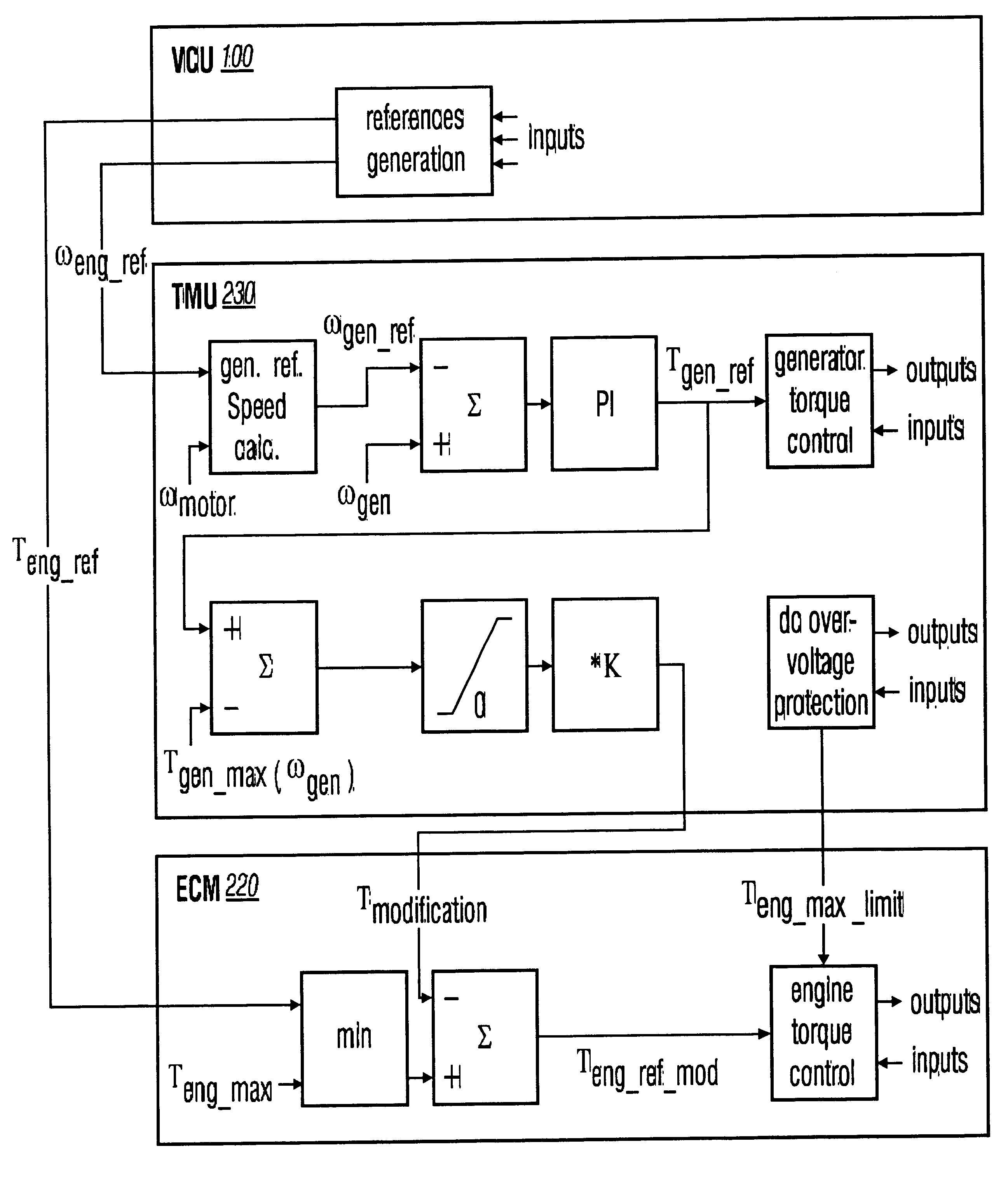
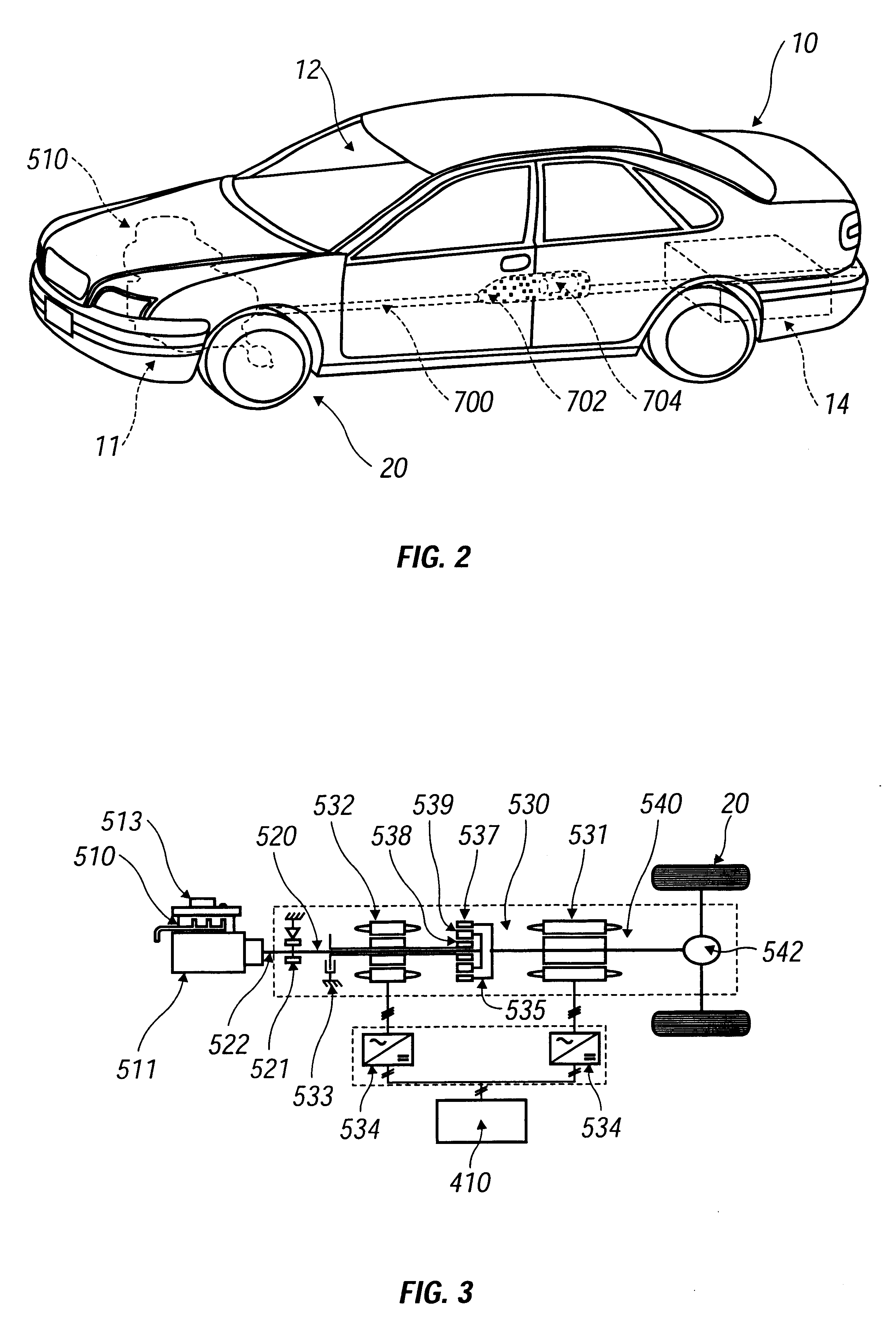
As depicted in FIGS. 1 and 2, a hybrid electric transporting vehicle 10 has a power train system (having components generally designated with reference numbers from the 500's series) included therein for providing propulsion, as well as serving supplemental functions which are described in greater detail herein. Predominantly, the power train system is positioned in an ...


PUM


Abstract

Method for potentiating the utilizable torque output capacity of a hybrid electric vehicle is provided. The method includes controlling operation of an engine of a hybrid electric vehicle using a generator, the engine and generator being interconnected through a planetary gear system, the generator having approximately equal torque output capacity as the engine based on connective gear ratio selection. An engine controller is utilized for managing the engine's operation thereby permitting the engine to be operated at a torque output level substantially equal to the maximum torque output of the generator without a significant margin of excess control capacity of the generator over the engine. An overpower condition is detected in which the torque output of the engine is surpassing the maximum torque output of the generator. The engine is controlled to a torque output that is less than the maximum torque output of the generator.

Description

DESCRIPTION1. Industrial ApplicabilityThe present invention finds applicability in the transportation industries, and more specifically private and commercial vehicles. Of particular importance is the invention's incorporation into hybrid electric vehicles.2. Background ArtGenerally, a hybrid electric vehicle combines electric propulsion with traditional internal combustion engine propulsion to achieve enhanced fuel economy and / or lower exhaust emissions. Electric propulsion has typically been generated through the use of batteries and electric motors. Such an electric propulsion system provides the desirable characteristics of high torque at low speeds, high efficiency, and the opportunity to regeneratively capture otherwise lost braking energy. Propulsion from an internal combustion engine provides high energy density, and enjoys an existing infrastructure and lower costs due to economies of scale. By combining the two propulsive systems with a proper control strategy, the result ...

Claims


Application Information

Patent Timeline
Patent Type & Authority Patents(United States)
IPC IPC(8): B60K6/00B60K6/04B60L15/20F02D41/02F02N17/00F02N17/08B60K6/445B60W10/06B60W10/08B60W10/26B60W20/00F02N19/00
CPCB60K6/445B60W10/06B60W10/08B60W10/26B60W20/00B60L15/2045Y02T10/6239B60L2240/421B60L2240/423B60L2240/441B60L2240/443B60W2510/0638B60W2510/0657B60W2510/081B60W2510/083B60W2710/0666F02D41/021F02D2250/18F02N19/00Y02T10/56Y02T10/6286Y02T10/7283Y02T10/642Y02T10/40Y02T10/62Y02T10/64Y02T10/72B60W20/30
Inventor OSTBERG, CLAESLASSON, ANDERS
Owner FORD GLOBAL TECH LLC
Why Eureka
Try Eureka