Vehicle height adjusting system

a height adjustment and vehicle technology, applied in the direction of wound springs, transportation items, gears, etc., can solve the problems of preventing a compact and economical design, large power consumption, and low mechanical efficiency of the worm gear mechanism, and achieve the effect of favorable support of reaction

Active Publication Date: 2007-09-13
HONDA MOTOR CO LTD
View PDF7 Cites 72 Cited by
  • Summary
  • Abstract
  • Description
  • Claims
  • Application Information

AI Technical Summary

Benefits of technology

[0017]In an arrangement that can favorable support the reaction arising from the meshing of the first drive gear and first driven gear, the first rotor is provided with a first disk around which the first driven gear is formed, and a central shaft integrally extending axially from the disk in a coaxial relationship and formed with a male thread for the threading coupling on an outer periphery thereof, and the second rotor is provided with a second disk around which the second driven gear is formed, the upper end of the first disk being formed with a recess coaxial with the first driven gear in which a boss depending from the opposing wall of the housing is rotatably received. Because the gear meshing point and the radial bearing support for the first driven gear may be located on a substantially same plane, the reaction arising from the meshing of the first drive gear and first driven gear can be supported in a favorable manner.

Problems solved by technology

However, the use of a worm gear mechanism having a relatively low mechanical efficiency gives rise to a number of problems.
Because a worm gear mechanism causes a significant torque loss, the electric motor is required to have a correspondingly large output, and this prevents a compact and economical design.
A large power consumption is also a problem.
However, the use of a ball screw mechanism not only increases the manufacturing cost but also creates the need to prevent the rotation of the female thread member to prevent unintended movement of the ball screw mechanism when an input from the road is applied thereto.
However, no such measure is described in this prior application.
Therefore, the resulting moment causes a tilting of the outer cylindrical member and this inevitably applies uneven loads to the threading engagement as well as to the spline engagement.

Method used


Image

  • Vehicle height adjusting system
  • Vehicle height adjusting system
  • Vehicle height adjusting system

Examples


first embodiment

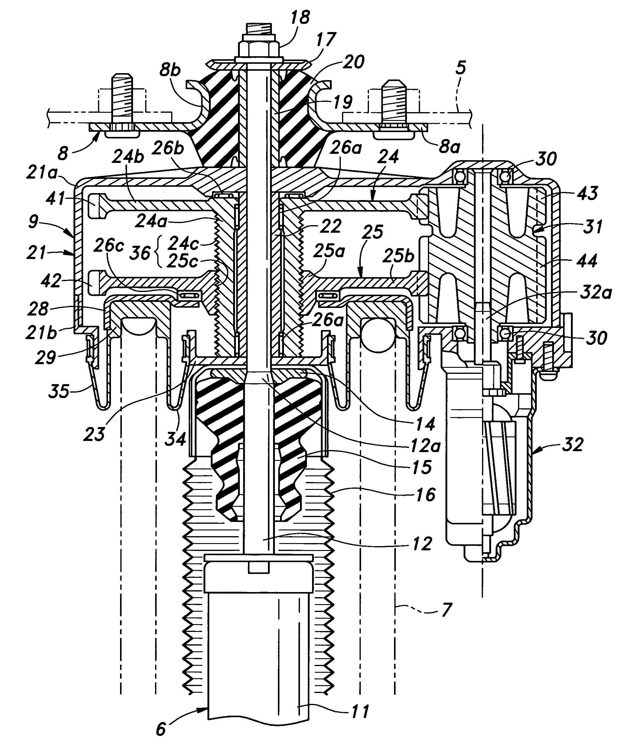
[0038]The mount plate assembly 8 comprises a plate main body 8a made of stamp formed steel plate and formed with a central boss 8b defining a central opening, a collar 19 fitted on the damper rod 12 and a cylindrical mount rubber 20 joining the central boss 8b of the plate main body 8a with the collar 19. The vehicle height adjusting system 9 of the first embodiment is interposed between the retaining ring 14 and the collar 19 secured to the mount plate assembly 8 via the mount rubber 20.

[0039]The vehicle height adjusting system 9 comprises an upper housing half 21a having the shape of an inverted cup and provided with a central opening through which the damper rod 12a passes and a lower housing half 21b fixedly secured to the lower edge of the upper housing half 21a to form a housing 21 for the vehicle height adjusting system 9 jointly with the upper housing half 21a and define a relatively large central opening. A center collar 22 is fitted on the damper rod 12 within the housing ...

second embodiment

[0053]FIG. 5 shows the present invention which is similar to the previous embodiment but differs only in the arrangement of the gears. In the following description of this embodiment in reference to FIG. 5, the parts corresponding to those of the previous embodiment are denoted with like numerals without repeating the description of such parts.

[0054]In this embodiment, the drive shaft 31 is provided with a single drive gear 45 which commonly meshes with both the first and second driven gears 41 and 42 which are similar to those of the previous embodiment. The drive gear 45 is accordingly provided with an adequate gear width that accommodates the simultaneous meshing with the two driven gears 41 and 42 and the expected axial movement of the second driven gear 42. The first and second driven gears 41 and 42 may have a same tooth profile and module, but may have different profile shifts (addendum modification coefficient) to ensure a favorable meshing of the gears. In this embodiment, ...

third embodiment

[0055]FIGS. 6 and 7 show the present invention which is similar to the previous embodiments. In the following description of this embodiment in reference to FIGS. 6 and 7, the parts corresponding to those of the previous embodiments are denoted with like numerals without repeating the description of such parts.

[0056]Referring to FIG. 6, an upper housing half 21a is provided with a relatively small vertical dimension, and a lower housing half 21b is provided with a cylindrical extension 21c extending downwardly in a central part of the lower housing half 21b. The upper housing half 21a, lower housing half 21b and the cylindrical extension 21c jointly form a housing 21.The inner circumferential surface of the cylindrical extension 21c defines a cylindrical surface somewhat eccentric to the axial center of the housing 21 through which the bumper rod 12 passes.

[0057]In this embodiment, a central collar 22 is fitted on the bumper rod 12 within the housing 21, and is provided with an uppe...


PUM


Abstract

A first rotor (24; 124) and a second rotor (25; 125) are arranged in a coaxial and mutually rotatable relationship and are provided with a first driven gear (41; 141) and a second driven gear (42; 142), respectively. A drive shaft (31; 131) is also provided with a first drive gear (43; 143) and a second drive gear (44; 144) which are commonly connected to an output shaft of an electric motor (32; 132), and mesh with the first and second driven gears, respectively, at slightly different gear ratios. The first and second rotors are connected via a thread feed mechanism (36; 136) that converts a relative rotation between the first and second rotors into an axial linear movement between the first and second rotors that is used for changing a distance between a vehicle body part and a corresponding end of a suspension spring in a vehicle height adjusting system (9; 109). Owing to a differential rotation of a high gear ratio between the first and second rotors, a significant torque amplification is possible with a compact arrangement. The use of spur gears instead of a worm gear mechanism minimizes torque loss.

Description

TECHNICAL FIELD[0001]The present invention relates to a vehicle height adjusting system for a wheel suspension system, and in particular to such a vehicle height adjusting system which is highly compact and light weight.BACKGROUND OF THE INVENTION[0002]Various types of vehicle height adjusting systems are known. Hydraulic systems and hydro-pneumatic systems are most commonly used for vehicle height adjusting systems. To the end of improving the control precision and simplifying the structure, a proposal has been made to use a worm gear mechanism or a ball screw mechanism powered by an electric motor (see Japanese patent laid open publication No. 11-108100). In this prior proposal, between an upper spring seat supporting an upper, end of a suspension spring and a vehicle body member is interposed a ball screw actuator mechanism. A rotor (male thread member) of the ball screw actuator mechanism is driven by an electric motor so that the space between the upper spring seat and vehicle ...

Claims


Application Information

Patent Timeline
Patent Type & Authority Applications(United States)
IPC IPC(8): B60G17/052B60G17/00B60G15/00
CPCB60G15/063B60G15/068B60G17/02B60G17/021B60G17/052Y10T74/18576B60G2204/1242B60G2204/128B60G2500/20B60G2500/30B60G2202/12
Inventor HAKUI, TAKEHIKOHIRATA, HAJIMEKAJIWARA, HAJIMENAKAJIMA, KIYOSHIAKUTA, YOSHIMITSUHATANO, KUNIMICHI
Owner HONDA MOTOR CO LTD
Why Eureka
Try Eureka