Design plan of (no-gap) type crankshaft driving piston reciprocating compressor

A technology of crankshaft drive and design scheme, which is applied in the direction of mechanical equipment, machine/engine, liquid variable displacement machinery, etc.

Inactive Publication Date: 2007-01-24
梁嘉麟
View PDF0 Cites 16 Cited by
  • Summary
  • Abstract
  • Description
  • Claims
  • Application Information

AI Technical Summary

Problems solved by technology

[0004] Purpose of the present invention: to solve the problem of the above-mentioned "no clearance" design of the existing piston reciprocating compressor

Method used


Image

  • Design plan of (no-gap) type crankshaft driving piston reciprocating compressor
  • Design plan of (no-gap) type crankshaft driving piston reciprocating compressor
  • Design plan of (no-gap) type crankshaft driving piston reciprocating compressor

Examples


Embodiment Construction

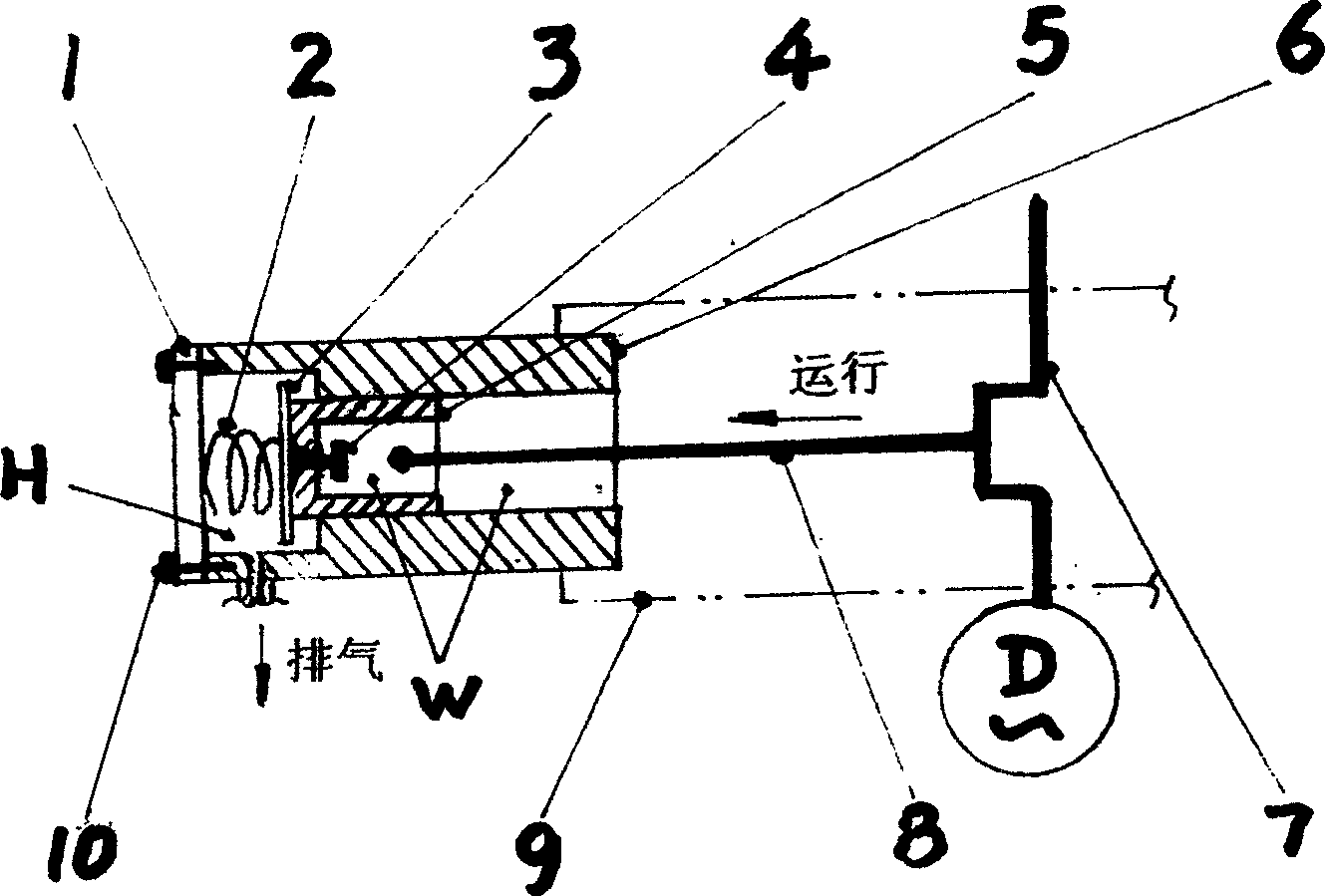
[0014] figure 1 The structural overview of the "backlash-free" design of the crankshaft-driven compressor is highlighted.

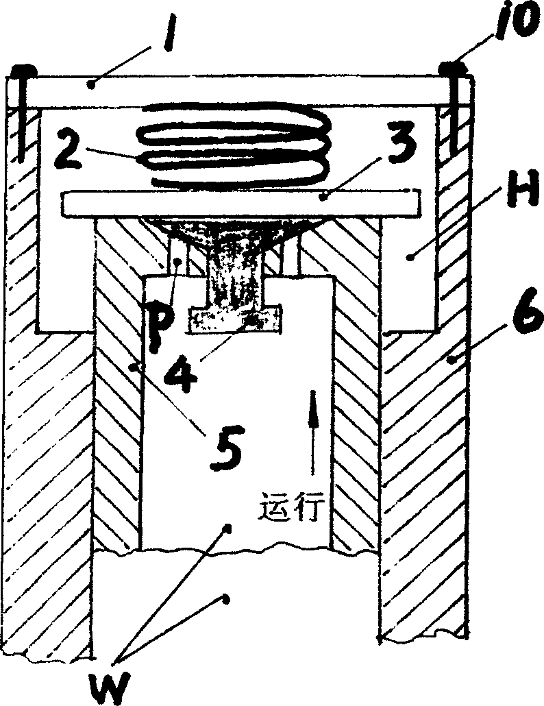
[0015] Depend on figure 2 As shown, the piston 5, which is doing compression and exhaust work, squeezes all the compressed high-pressure gas into the high-pressure zone H, and then it continues to press the exhaust valve plate 3 and rush out of the cylinder 6, and enters the high-pressure zone H. At this time, the geometric space ("clearance") between the piston 5, the conical suction valve block 4 and the exhaust valve plate 3 is not difficult to reach extremely close to "zero", or even equal to "zero". . The stroke of the piston 5 rushing out of the cylinder 6 can usually be controlled at about 1 / 10 of its effective suction stroke length.

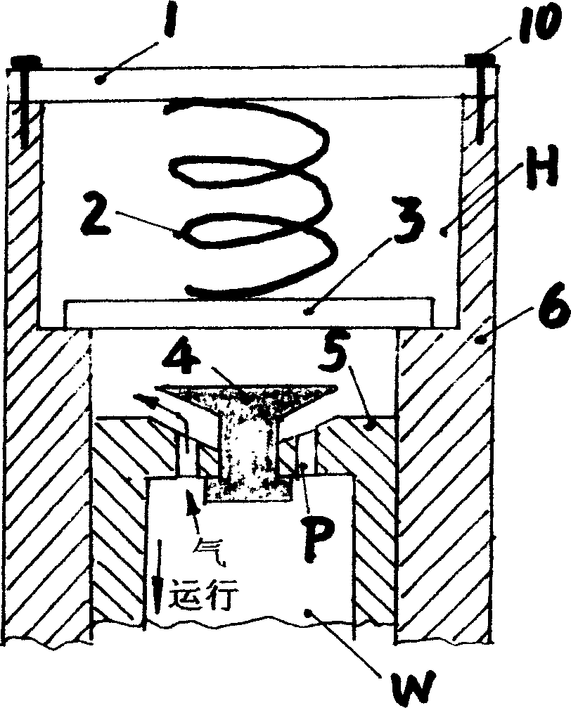
[0016] Depend on image 3 As shown, when the piston 5 fully retracted into the cylinder 6, the exhaust valve plate 3 positioned by the spring 2 would naturally allow it to be driven by high air pressure to seal...


PUM


Abstract

The disclosed design scheme is based basic structure of traditional crankshaft drive model piston reciprocating type compressor with largest quantity of production and marketing in world. Characters are that when carrying out exhaust operation, carrying out vent valve, piston dashes out cylinder entering into high-pressure area. Thus, 'no clearance' state with no geometrical space is formed among piston, vent valve piece, and block of suction valve. Hermetically sealed construction of tapering shape cover is formed between block of suction valve and contact surface outside top part of piston. The invention creates condition for raising operational compression ratio or exhaust efficiency for the model of compressor.

Description

Technical field: [0001] The invention relates to crankshaft-driven piston compressor technology. Background technique: [0002] The vast majority of compressors that are currently available are conventional piston compressors driven by crankshafts, which have the advantages of simple manufacture, long service life, and low material requirements, which cannot be compared with other types of compressors. This is the main reason why it has been enduring since its inception. [0003] However, its disadvantages are as follows: it is difficult to improve its working compression ratio or exhaust efficiency. And one of the main reasons why it is difficult to improve and stagnate is exactly: it is difficult to improve its "volume" efficiency structurally, that is, to reduce the design efficiency of its "clearance" structurally, and the "clearance" mentioned in the title of the present invention No clearance" design is unimaginable. Invention content: [0004] Purpose of the pres...

Claims


Application Information

Patent Timeline
Patent Type & Authority Applications(China)
IPC IPC(8): F04B27/08
Inventor 梁嘉麟
Owner 梁嘉麟
Why Eureka
Try Eureka