Novel bath tub using microwave energy heating control water temperature

A heating control and microwave heater technology, applied in microwave heating, water heaters, fluid heaters, etc., can solve the problems of affecting heating effect, electric shock, endangering people's lives, etc., and achieve the effect of small microwave leakage and ensuring safety.

Inactive Publication Date: 2007-01-24
王宝根
View PDF0 Cites 1 Cited by
  • Summary
  • Abstract
  • Description
  • Claims
  • Application Information

AI Technical Summary

Problems solved by technology

[0002] At present, the electric heating tube is generally used to control the water temperature in the bathtub to not drop, and the water will conduct electricity. If the electric heating tube is placed in the water, although there is a leakage protection device, it cannot be guaranteed to be foolproof, especially after long-term use. Electric shock accidents endanger people's lives; electric heating tubes will accumulate scale after long-term use, which will affect the heating effect

Method used


Image

  • Novel bath tub using microwave energy heating control water temperature
  • Novel bath tub using microwave energy heating control water temperature
  • Novel bath tub using microwave energy heating control water temperature

Examples


Embodiment 1

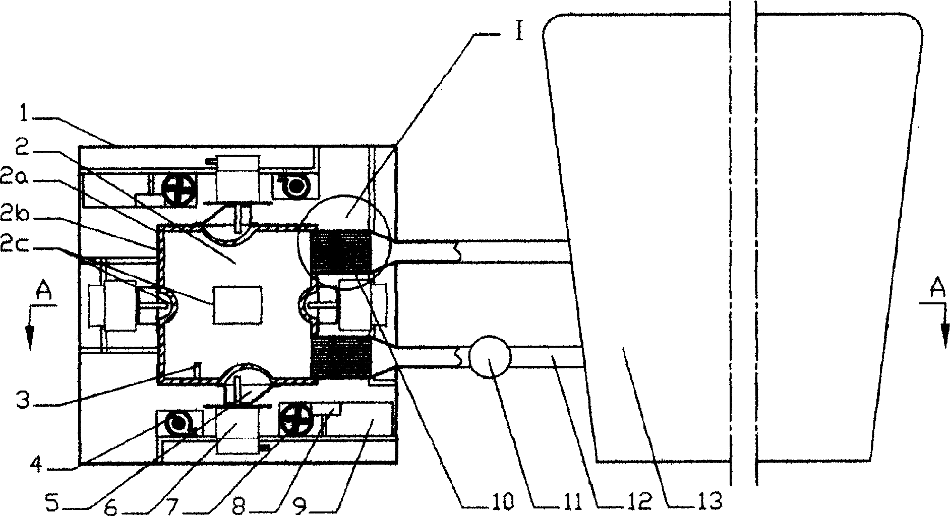
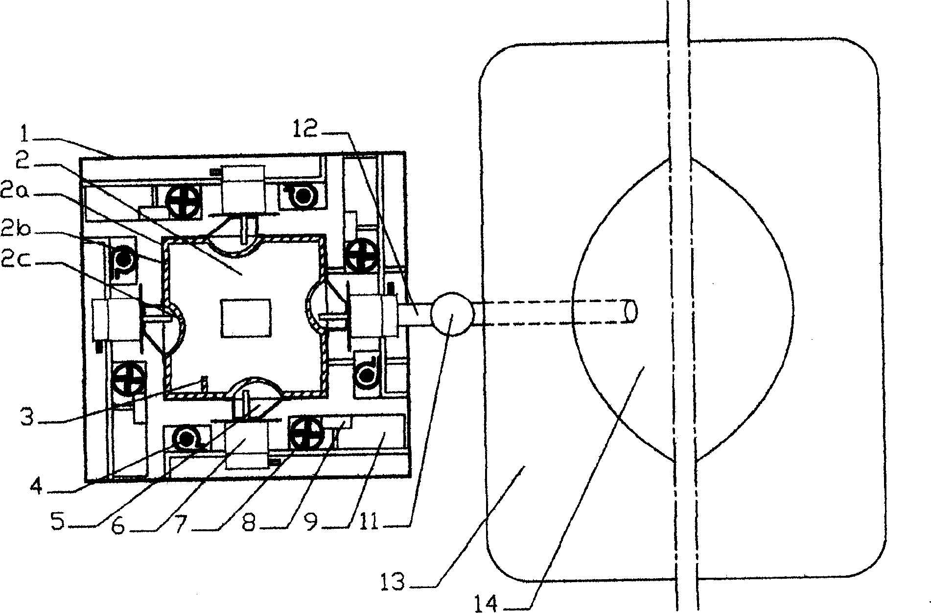
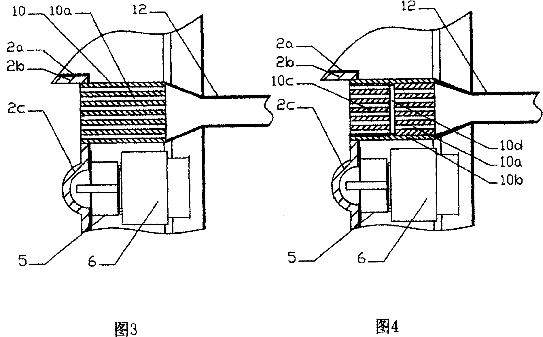
[0016] Example 1 The structure of the new bathtub of this example can be obtained from figure 1 with figure 2 It can be seen that the bathtub reservoir 14 is connected to a microwave heater 2. The microwave heater 2 is a cube, which is composed of an inner layer 2b microwave-transmitting material such as glass fiber reinforced plastic and an outer layer 2a microwave-opaque material such as stainless steel. Each of the six surface centers of the inner layer 2b of the device 2 has a heating port 2c with a square bottom and a spherical groove shape. The outer layer 2a at the heating port 2c has a square opening and then a waveguide 5 and a magnetron are fixed. Tube 6, the six magnetrons 6 are divided into three groups according to opposite faces to work in turn to extend the service life of the components. The microwave heater 2 communicates with the bathtub water storage tank 14 through two energy conversion tubes 10 and a water inlet and outlet pipe 12, and a booster pump 11 is i...

Embodiment 2

[0020] Example 2 The structure of the new bathtub of this example can be obtained from Figure 5 with Figure 6 It can be seen that it is different from embodiment 1 in that: the microwave heater 2 is set in the bathtub, that is, it is formed by a partition 15 arranged with a circulation mesh 15a with a diameter of less than 3 mm and the bottom of the bathtub water tank 14 In the cavity, there are four heating ports 2c with a square bottom and a spherical groove shape on the bottom surface of the bathtub water tank 14, such as Figure 5 As shown by the dotted line in the middle; a magnetron 6 and its power supply and heat dissipation components, namely transformer 9, capacitor 8, centrifugal fan 4 and axial fan 7 are respectively fixed in the inner cavity 16 under the heating port 2c.

[0021] There is a retaining ring 17 in the microwave heater 2 which is in full contact with the bottom of the partition 15 and the bottom of the water storage tank 14; in the bathtub cavity 16 there...


PUM


Abstract

Water storage trough of the new type bathtub is connected to microwave heater. When temperature sensor inside the microwave heater has measured that water temperature inside the bathtub lowers to a certain degree, the invention starts up magnetron to heat water inside the microwave heater. Through effect of heat conduction, water temperature inside the bathtub is raised so as to reach purpose of controlling temperature. The microwave heater could be as a cube, and is produced from composite materials: microwave transmission material in inner layer, and material impermeable to microwave in outer layer; or being setup in the bathtub, the microwave heater is produced from clapboard of circulation mesh with diameter less than 3mm enclosed by bottom face of water storage trough of bathtub. Features are: no risk of electric shock, no water fouling, energy saving, safe and reliable.

Description

1. Technical Field [0001] The invention relates to a method for heating water in a bathtub, in particular to a novel bathtub that uses microwave energy heating to control the water temperature in the bathtub. 2. Background technology [0002] At present, the heating of the water in the bathtub to control the water temperature does not drop generally uses an electric heating tube, and the water will conduct electricity. The electric heating tube is placed in the water. Although there is a leakage protection device, it cannot be guaranteed to be foolproof, especially after long-term use. Electric shock accidents endanger people's lives; after long-term use, the electric heating tube will form scale and affect the heating effect. Third, the content of the invention [0003] The purpose of the present invention is to solve the above-mentioned problems and provide a new type of bathtub, which can use microwave energy to conduct non-contact radiation heating of the water in the bathtu...

Claims


Application Information

Patent Timeline
Patent Type & Authority Applications(China)
IPC IPC(8): F24H1/18H05B6/64
Inventor 王宝根
Owner 王宝根
Why Eureka
Try Eureka