Converter for changing three phase power into single phase power

A technology of three-phase power supply and single-phase power supply, applied in the direction of circuit devices, electrical components, AC network circuits, etc., can solve the problems of three-phase power supply grid power imbalance, grid power supply deterioration, damage, etc., to achieve reasonable and effective use , Ensure safe and efficient operation, simple and reasonable structure design

Inactive Publication Date: 2007-01-24
熊晓强
View PDF0 Cites 9 Cited by
  • Summary
  • Abstract
  • Description
  • Claims
  • Application Information

AI Technical Summary

Problems solved by technology

However, in the actual use process, due to the insufficient power distribution of the grid and the uncertainty of the use time of single-phase power appliances, the grid power consumption of the three-phase power supply is often unbalanced, and the grid voltage is unstable, especially in power shortage areas and power consumption peaks. During this period, it may even cause the electrical equipment on the power grid to be unable to use normally or be damaged, and may also

Method used


Image

  • Converter for changing three phase power into single phase power
  • Converter for changing three phase power into single phase power
  • Converter for changing three phase power into single phase power

Examples


Embodiment 1

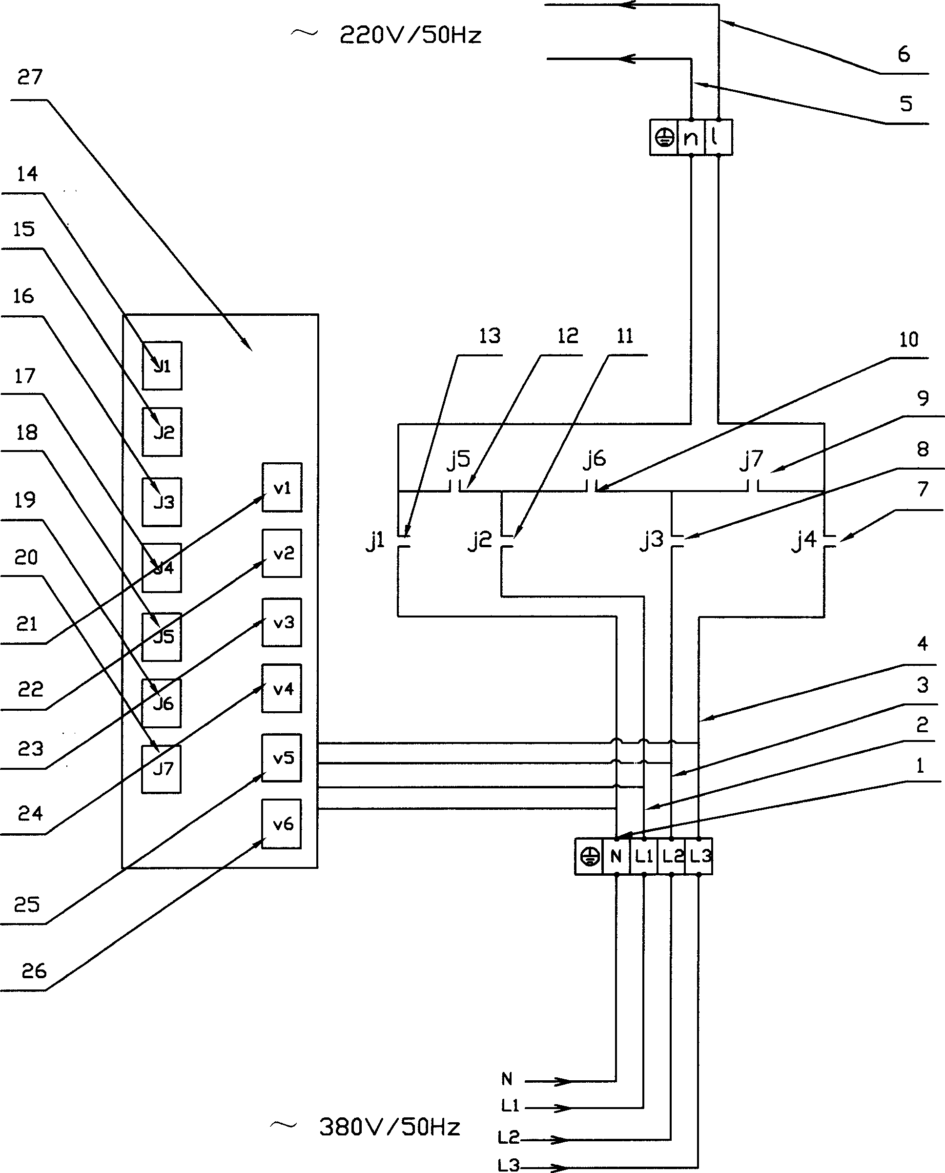
[0016] Embodiment 1, with reference to figure 1 . A three-phase power-to-single-phase power conversion device, comprising three-phase power input lines N(1), L1(2), L2(3), L3(4), single-phase power supply output lines n(5), l(6), voltage processor (27), main relay J1(14), J2(15), J3(16), J4(17), J5(18), J6(19), J7(20), voltage Transformers V1(21), V2(22), V3(23), V4(24), V5(25), V6(26), the voltage transformers V1(21), V2(22), V3(23 ), V4(24), V5(25), V6(26) and main relays J1(14), J2(15), J3(16), J4(17), J5(18), J6(19), J7 (20) Distributed on the voltage processor (27), the input lines N(1), L1(2), L2(3), and L3(4) of the three-phase power supply are respectively connected to the voltage processor (27) by wires , provide the driving power of the voltage processor (27), and make the input terminals of the voltage transformer V1 (21) be connected with the input lines N (1) and L1 (2) of the three-phase power supply respectively, and the voltage transformer V2 (22 ) input te...

Embodiment 2

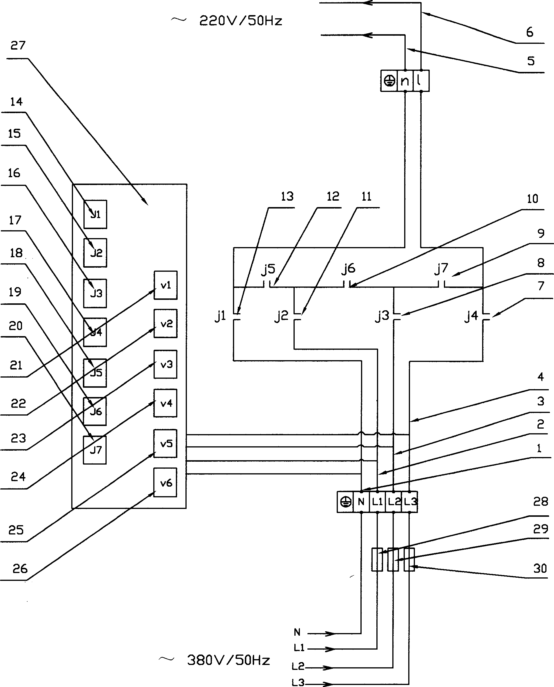
[0018] Embodiment 2, with reference to attached figure 2 . The difference between Embodiment 2 and Embodiment 1 is that fuses (28) and (29 ), (30) or leakage switch.

Embodiment 3

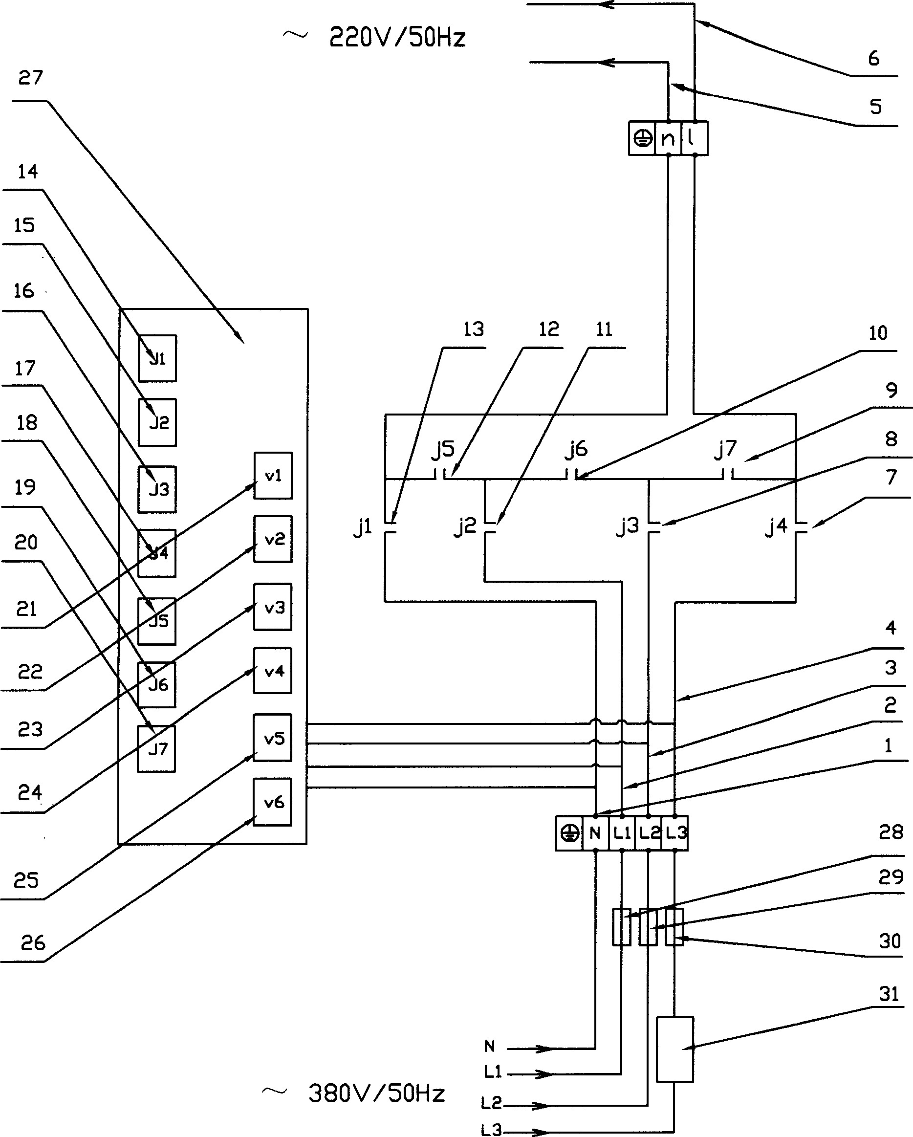
[0019] Embodiment 3, with reference to attached image 3 . The difference between embodiment 3 and embodiment 2 is that: on the input lines L1(2), L2(3), and L3(4) of the three-phase power supply, a phase line can be arbitrarily selected to add a voltage-reducing transformer (31 ) or other voltage-reducing devices, the driving power supply of the voltage processor (27) cannot adopt the power supply after the voltage reduction.

[0020] The working principle is as follows: when the voltage between the input lines L1(2), L2(3), L3(4) and N(1) of the three-phase power supply is higher than the output lines n(5), l(6) of the single-phase power supply ) requirements, by selecting the phase line of the transformer (31) for step-down voltage, it is easy to meet the requirements for the use of the output lines n(5), l(6) of the single-phase power supply; when the input line L1(2) of the three-phase power supply ), the voltage between L2(3), L3(4) and N(1) is lower than the requireme...


PUM


Abstract

This invention relates to a supply device including: the input lines of a three-phase supply N, L1, L2 and L3, output line of a single-phase supply n, 1, a voltage processor, main relays J1, J2, J3, J4, J5, J6 asnd J7 and voltage mutual-inductors V1, V2, V3, V4, V5 and V6. This simple structure can provide most suitable supply to single-phase supply applicances, which either guarantees their normal use in the region net or automatically balances the three-phase supply net and provides the ideal supply condition for single-phase supply applicances to guarantee power devices and supply applicances to operate efficiently and selects three-phase voltages to be used for single supply when the net is at the super-low voltage.

Description

technical field [0001] The invention relates to a power supply device, in particular to a three-phase power supply to single-phase power conversion device. Background technique [0002] In today's rapid economic development, energy shortage has become the main factor hindering economic development. Reasonable and effective use of energy and energy conservation will play a positive role in the development of social economy. Electric energy is one of the most important energy sources in our daily work and life. The current electric energy in our country is mainly single-phase and three-phase power supply. The single-phase power supply is 220V / 50Hz, and the three-phase power supply is 380V / 50Hz. As far as a region or factory is concerned, some of the general electrical equipment are three-phase power supply, some are single-phase power supply, and some are combination equipment of three-phase power supply and single-phase power supply; and the power supply for these equipment h...

Claims


Application Information

Patent Timeline
IPC IPC(8): H02J3/00H02J3/26
CPCY02E40/50
Inventor 熊晓强
Owner 熊晓强
Why Eureka
Try Eureka