Panel display device and panel display device setting device

A flat-panel display and equipment technology, which is used in the identification of parts of devices, instruments, and television systems, etc., can solve problems such as misoperation and failure of equipment, and achieve the goal of solving heat dissipation problems, easy installation, and long-term stable operation of flat-panel display equipment. Effect

Inactive Publication Date: 2007-01-24
NANJING LG TONGCHUANG COLOR DISPLAYS SYST CO LTD
View PDF0 Cites 1 Cited by
  • Summary
  • Abstract
  • Description
  • Claims
  • Application Information

AI Technical Summary

Problems solved by technology

[0004] On the other hand, although this kind of flat-panel display device is small in size and can provide convenience for users, it is an important problem to solve the heat dissipation during module startup due to the limitation of gathering in a narrow flat-type space during production.
In particular, in the PDP device, high-temperature heat is generated by the discharge phenomenon of the discharge gas and the entire assembly, and if this heat is not released, it may actually become a major factor for device misoperation or failure.

Method used


Image

  • Panel display device and panel display device setting device
  • Panel display device and panel display device setting device
  • Panel display device and panel display device setting device

Examples


Embodiment 1

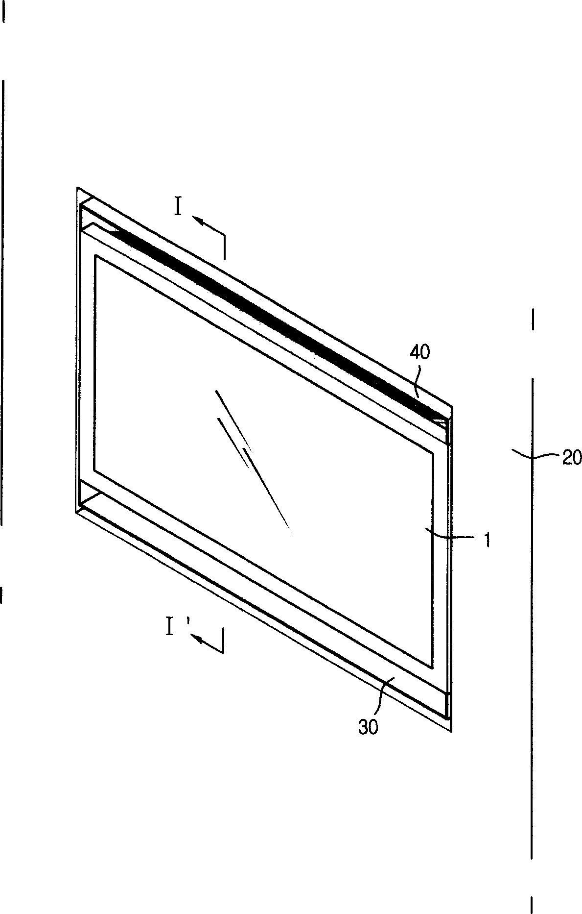
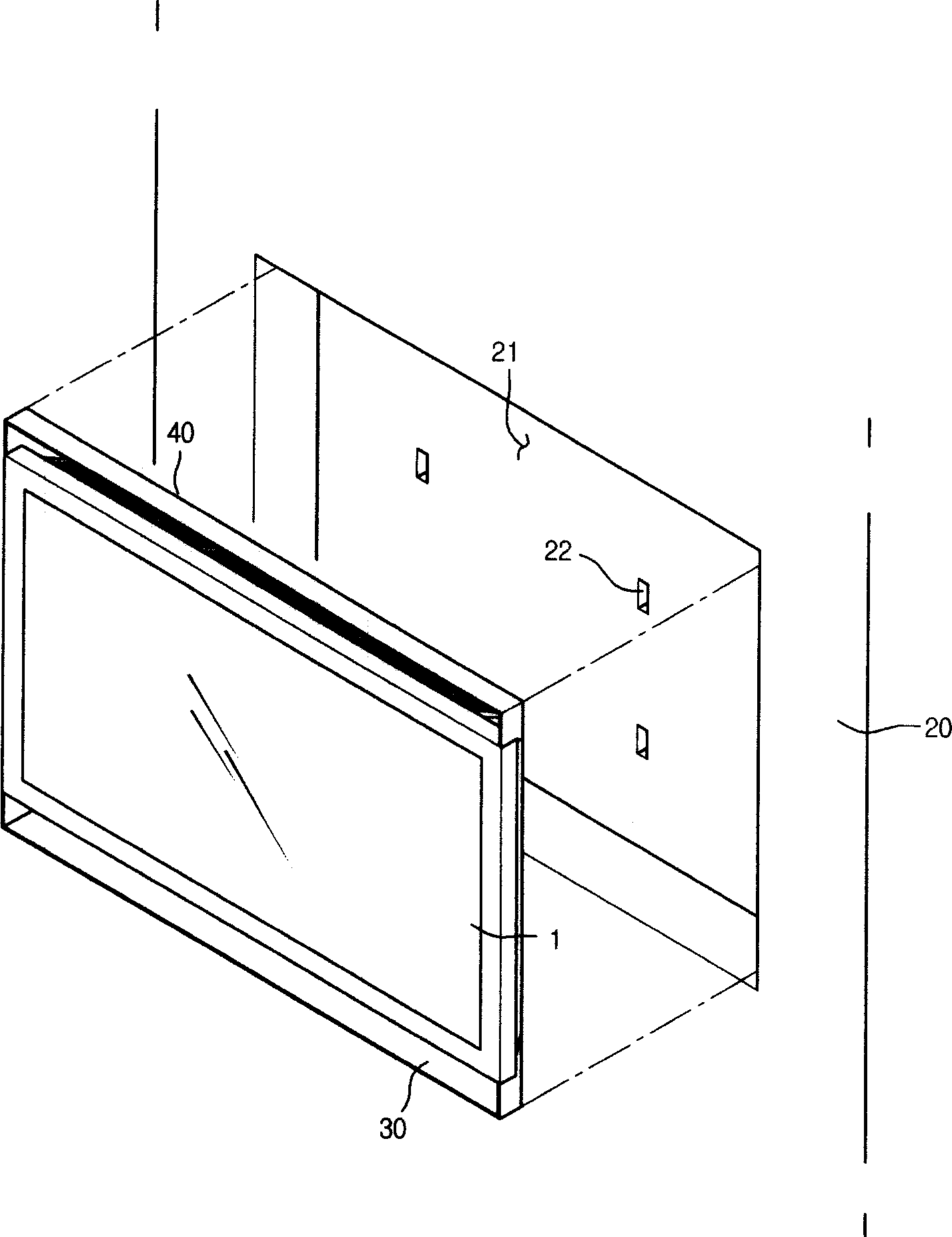
[0052] Example 1: figure 1 It is an oblique view of the setting device of the plane display device of the present invention, figure 2 It is an example picture of the set part and the disassembled state of the planar display instrument in the setting device of the planar display instrument of the present invention.

[0053] refer to figure 1 and figure 2 , it is a feature of the planar display device of the present invention that the planar display device is embedded in the receiving groove 21 of the set part 20 at a certain depth, and the related structure will be introduced in detail below.

[0054] The above-mentioned set part 20 is an object on which the flat-panel display device 1 is installed, and can be any object with a certain area and thickness such as the wall surface of an indoor space, a subway pillar, a building exterior wall, a vehicle body, etc. Of course, as long as the above-mentioned flat-panel display can be provided Machine 1 is provided with the requi...

Embodiment 2

[0090] Other parts of the 2nd example of the present invention are the same as the 1st example already introduced, only the specific shape characteristics of the inflow channel and the outflow channel are different. Therefore, the part that does not specifically introduce this example is the introduction of the above-mentioned first example.

[0091] Figure 8 It is an exploded oblique view showing the instrument, the inflow channel and the outflow channel in the second example of the present invention.

[0092] refer to Figure 8 , the air flow in the planar display device 1 is the same as that already introduced, and the specific shapes of the above-mentioned inflow guide groove 50 and outflow guide groove 60 are different. The specific introduction is as follows: the cross-sectional shape of the guide film that switches the air flow direction from the above-mentioned inflow guide groove 50 is curved, and the curve is smooth to form a curved inflow guide film 51. The above...


PUM


Abstract

The present invention relates to a panel display device, including a panel display module; a casing for protecting the outside of said panel display module; a cold air intake positioned on one side of said casing; a hot air outlet positioned on the other side of the casing; a blower installed on said hot air outlet; an inflow guiding groove for guiding the air inflowing through the cold air intake; an outflowing guiding groove for guiding the air outflowing through the hot air outler. The panel display device has the advantage of solving the problem of heat dissipation by setting the panel display device closely in a confined space. As a result, the panel display device can be positioned closely in a confined space in a best mode, and the positioning of the panel display is easiest and the reliability of the operating of the panel display device is improved.

Description

technical field [0001] The present invention is an invention related to a flat display device, more specifically, an invention related to an installation device for a flat display device that can be easily installed on a wall or the like and can be used safely. More specifically, the object is to propose an installation device for a flat-panel display device that can be stably installed while easily removing high heat in the flat-panel display device. Background technique [0002] Different from ordinary cathode tubes, flat-panel display devices reflect the light-emitting state of each pixel according to the activation circuit arranged in a matrix form, thereby forming an overall screen device. Unlike the above-mentioned cathode tubes, this type of flat display device is small in size, so it occupies little space in a narrow indoor space, and has a high degree of consumer recommendation, and its usage rate has recently been significantly increasing. The flat-panel display m...

Claims


Application Information

Patent Timeline
Patent Type & Authority Applications(China)
IPC IPC(8): H05K7/18H05K7/20G09F9/00
CPCH04N5/64H05K7/20954
Inventor 金洪圻
Owner NANJING LG TONGCHUANG COLOR DISPLAYS SYST CO LTD
Why Eureka
Try Eureka