Supercharge Your Innovation With Domain-Expert AI Agents!

Device and method for temperature control in an aircraft cabin

A temperature control, cabin technology, used in aircraft parts, air handling equipment, transportation and packaging to solve problems such as unrealistic supply of heated air

Inactive Publication Date: 2007-01-24
AIRBUS OPERATIONS GMBH
View PDF0 Cites 4 Cited by
  • Summary
  • Abstract
  • Description
  • Claims
  • Application Information

AI Technical Summary

Problems solved by technology

[0017] Thereafter, the supply of heated air from valve 78 to non-faulty valves 60-64 by opening valve 88 is not possible since the failed valve 58 is also supplied with heated air.

Method used


Image

  • Device and method for temperature control in an aircraft cabin
  • Device and method for temperature control in an aircraft cabin
  • Device and method for temperature control in an aircraft cabin

Examples


Embodiment Construction

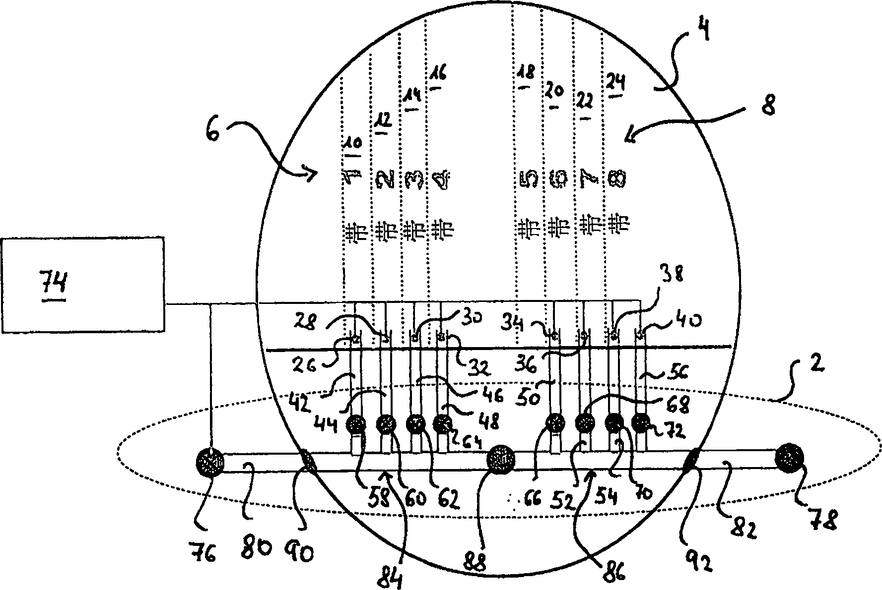
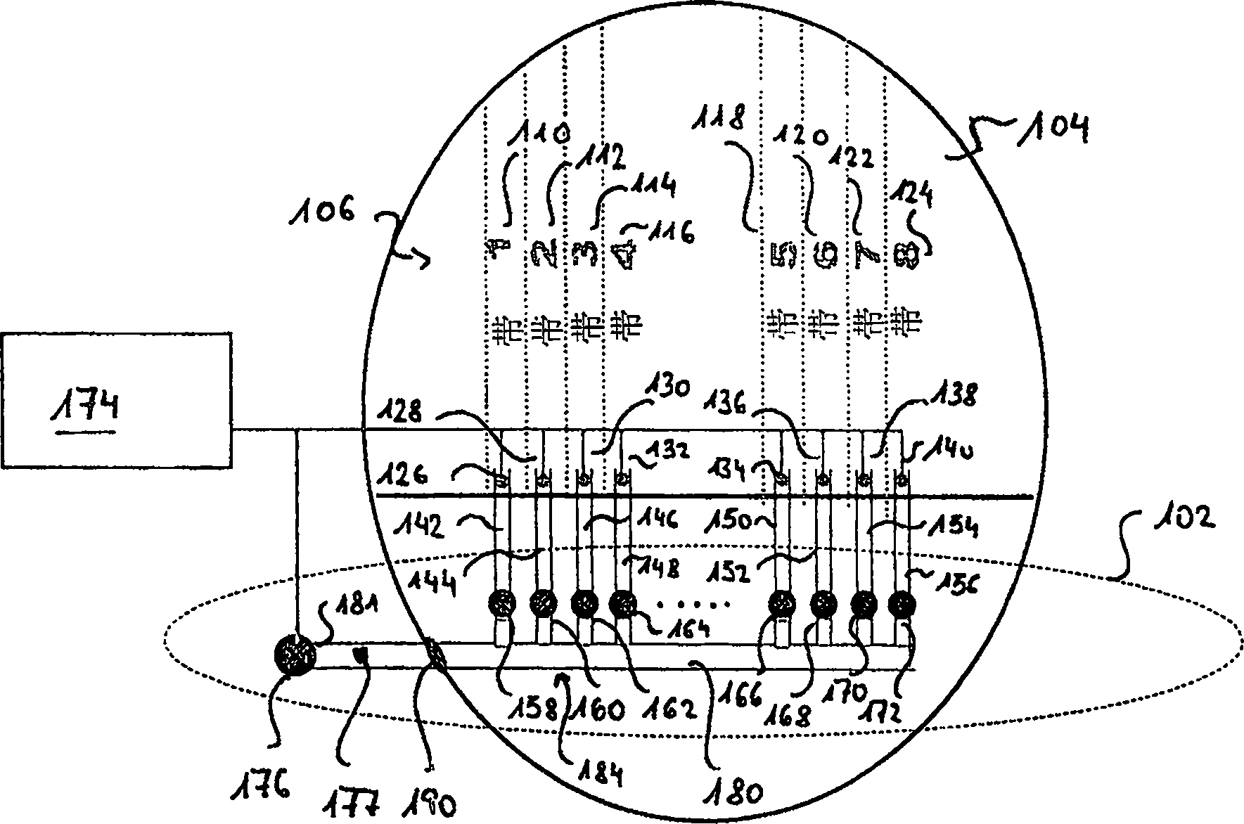
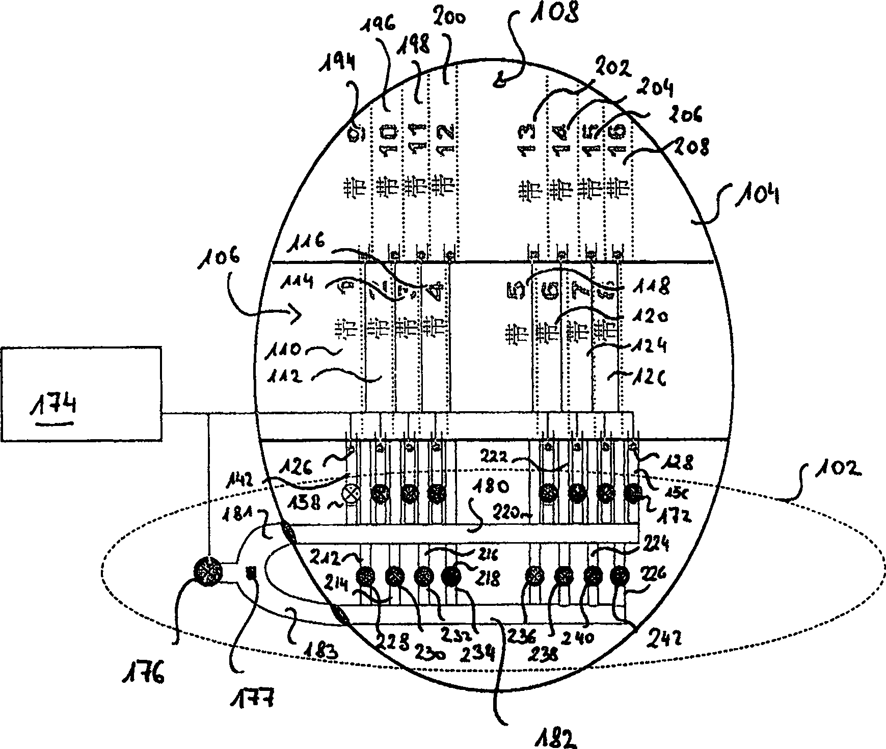
[0051] figure 1 An embodiment of a system 102 for temperature control in an aircraft cabin 104 , in particular in a temperature region 106 of the aircraft cabin 104 , is shown.

[0052] The temperature region 106 is divided into individual adjacently disposed temperature zones 110-124. The temperature sensors 126-140 are used to detect the temperature currently prevailing in the temperature zones 110-124. The temperature sensors 126-140 are arranged in outlet regions of air outlet ducts 142-156 through which heated air is supplied to the temperature zones 110-124.

[0053] To control the supply of heated air in the temperature zones 110-124, valves 158-172 are provided in the air outlet ducts 142-156, respectively. Based on the signals / data from the temperature sensors 126 - 140 , the controller 174 controls the valves 158 - 172 to achieve the temperature specified for the temperature zone 106 .

[0054] Heated air generated by one or more turbines of the aircraft propeller...


PUM


Abstract

A device for temperature control in an aircraft cabin includes a first supply control arrangement and a first pressure control arrangement. The first supply control arrangement includes an air duct and a valve arrangement that controls a supply of heated air delivered to a first temperature area of the aircraft cabin such that a first specified temperature for the first temperature zone is achieved. When the valve arrangement fails, the first pressure control arrangement operates to control a pressure of heated air supplied into the first temperature area such that the first specified temperature for the first temperature zone is achieved.

Description

technical field [0001] The present invention generally relates to temperature control in aircraft cabins. Background technique [0002] For temperature control in aircraft cabins, a commonly used system is to extract hot exhaust air from the turbines of the aircraft drives. This hot air, called drive unit exhaust air, is cooled to the temperature required in the aircraft cabin. In an aircraft, the aircraft cabin is divided into different temperature zones or climate zones, and a portion of the hot air is cooled to the lowest temperature of one or more temperature zones. In order to obtain a higher temperature in other temperature areas, part of the hot air is diverted before it is cooled to the minimum temperature, and it is cooled to a slightly lower degree to thereby reach a temperature higher than the minimum temperature, and it is compared with the temperature already cooled to the minimum temperature. The temperature of the air is mixed so that the desired temperature...

Claims


Application Information

Patent Timeline
Patent Type & Authority Applications(China)
IPC IPC(8): B64D13/08
CPCB64D2013/064B64D13/08
Inventor 尼科·森托凡特马库斯·彼得拉克托马斯·舍雷尔乌韦·布克霍尔斯
Owner AIRBUS OPERATIONS GMBH
Features
  • R&D
  • Intellectual Property
  • Life Sciences
  • Materials
  • Tech Scout
  • Unparalleled Data Quality
  • Higher Quality Content
  • 60% Fewer Hallucinations
Learn More