Radial valve orificing axial hydraulic pressure plunger pump

A hydraulic column and axial technology, applied in variable capacity pump parts, parts of pumping devices for elastic fluids, pumps, etc., can solve the problem of difficult maintenance and replacement of valve body accessories, inconvenient maintenance and replacement, Easy to wear and fail and other problems, to achieve the effect of shortening maintenance time, reducing structural size and good sealing performance

Inactive Publication Date: 2007-01-31
HUAZHONG UNIV OF SCI & TECH
View PDF0 Cites 22 Cited by
  • Summary
  • Abstract
  • Description
  • Claims
  • Application Information

AI Technical Summary

Problems solved by technology

The pump has the advantages of small size, light weight, and high specific power. The key friction pair of heavy load is easy to wear and fail, which brings inconvenience to maintenance and replacement. Therefore, engineering ceramic materials are mostly used for this pair of friction pair, but its processing cost is high and it is also very difficult in the design and manufacturing process.
However, due to the axial arrangement of its flow distribution valve (suction valve and discharge valve), its structure is more complicated, its volume is larger than other pumps with the same flow rate, and it is extremely difficult to maintain and replace the accessories of the valve body.

Method used


Image

  • Radial valve orificing axial hydraulic pressure plunger pump
  • Radial valve orificing axial hydraulic pressure plunger pump
  • Radial valve orificing axial hydraulic pressure plunger pump

Examples


Embodiment Construction

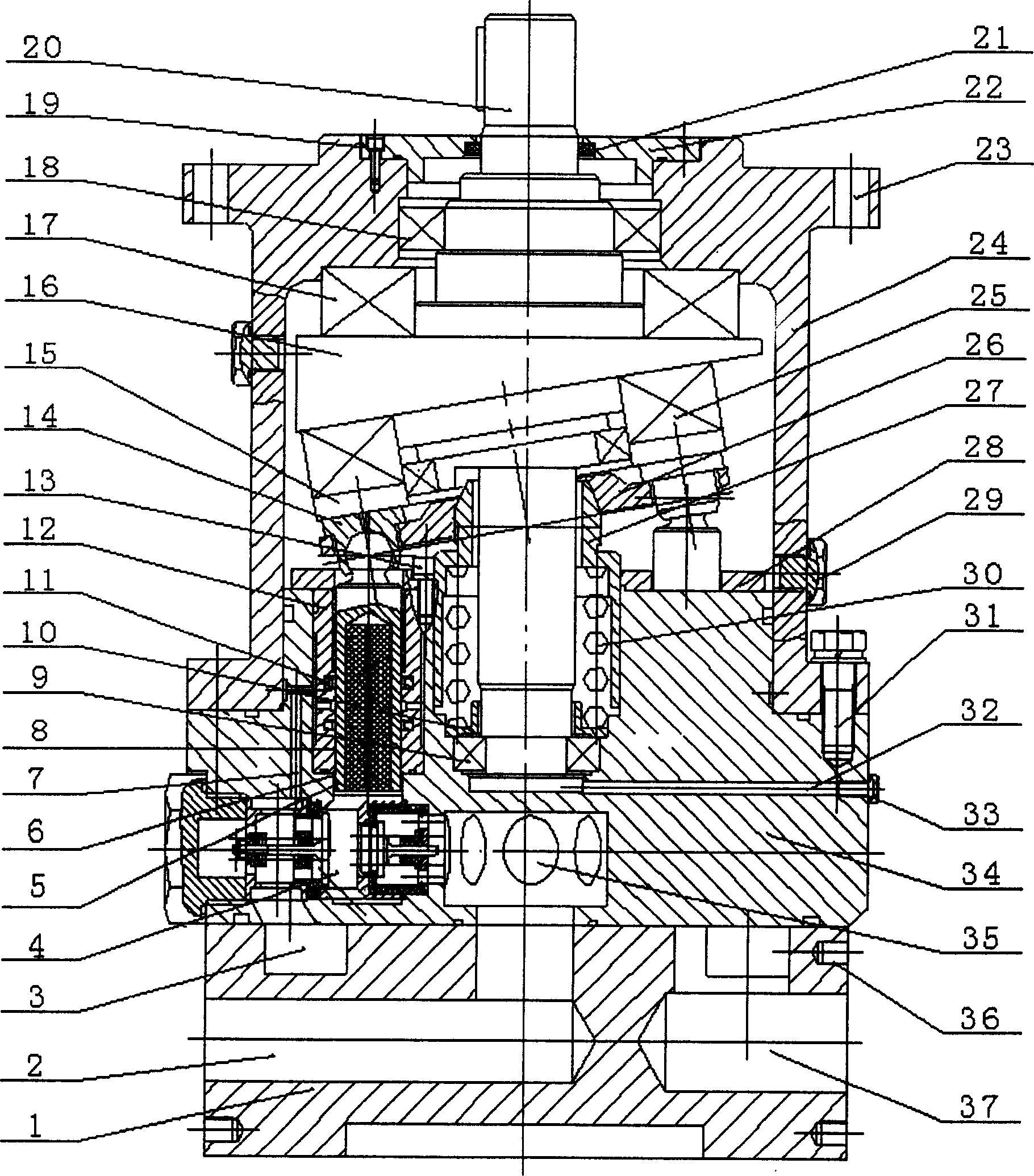
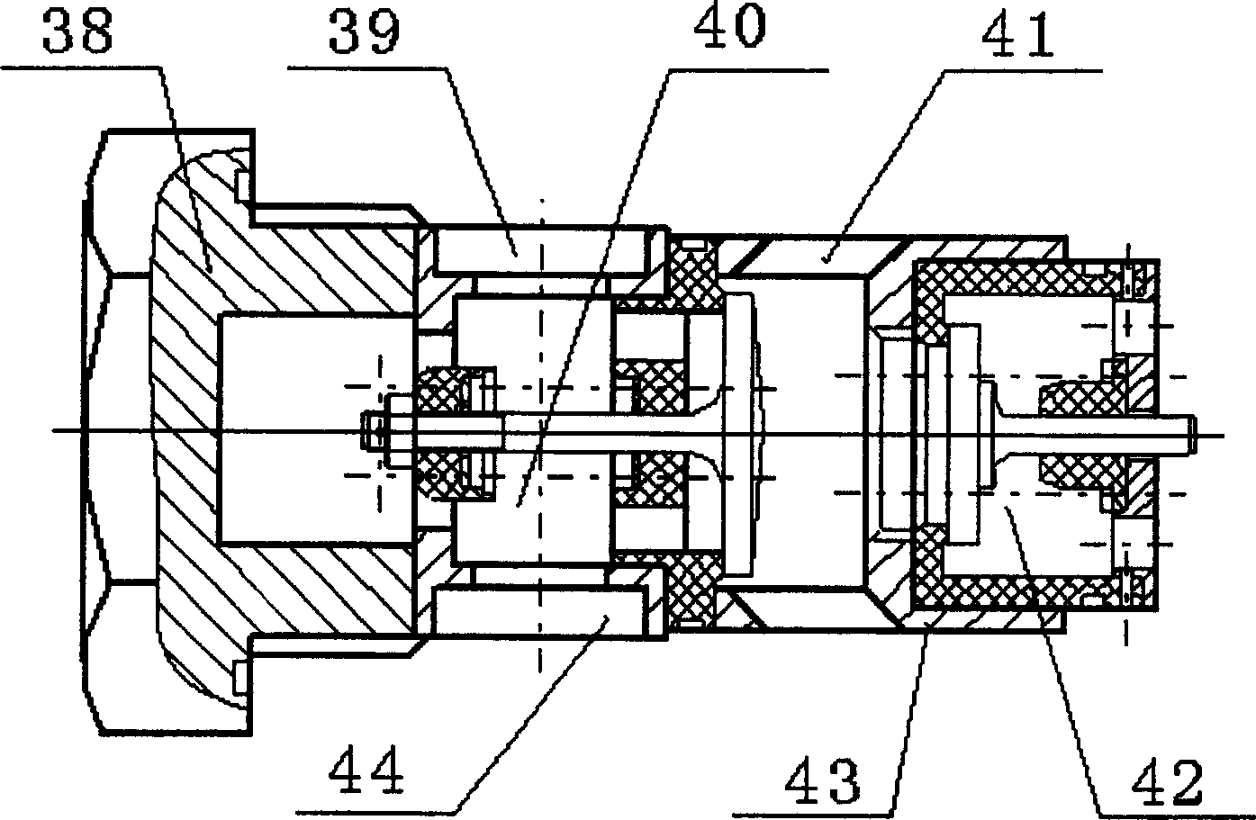
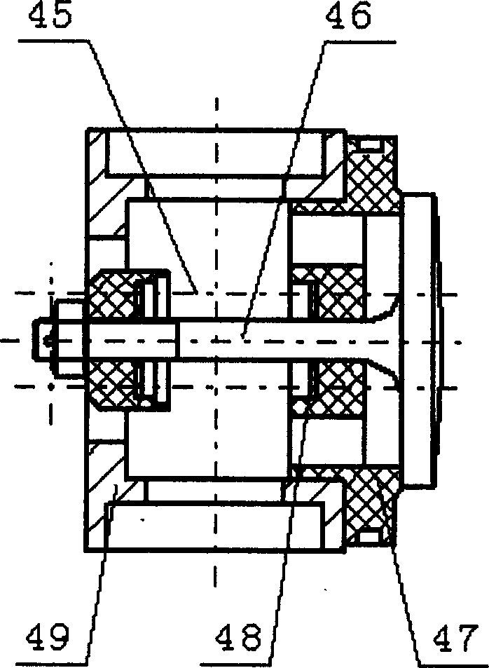
[0022] refer to Figure 1 ~ Figure 4 , the labels in the figure are: rear end cover 1, water outlet 2, annular groove 3, distribution valve body 4, plunger 5, plunger hole 6, water diversion channel 7, friction surface 8, deep groove ball bearing 9, spring seat 10. Rubber-plastic composite seal 11, plunger sleeve 12, compression screw 13, sliding shoe 14, swash plate 15, main shaft disc 16, thrust bearing 17, angular contact ball bearing 18, front end cover screw 19, main shaft 20, Oil seal ring 21, front end cover 22, positioning hole 23, pump body 24, ball bearing 25, return plate 26, ball hinge 27, pressure plate 28, screw plug 29, center spring 30, positioning screw 31, sewage outlet 32, plug 33. Cylinder body 34, central concave hole water outlet 35, screw hole 36, water inlet 37, distribution valve nut 38, suction valve port 39, suction valve 40, distribution valve port 41, pressure outlet valve 42, middle sleeve 43 , Suction valve inlet 44, Suction valve spring 45, Suc...


PUM


Abstract

In the invention, an inclined disk is bound on the mainshaft disk at the bottom of the mainshaft and on the inclined disk are uniformly set piston shoes in the flexible connection with the plunger. The plunger hole uniformly set on the cylinder is fitted with the plunger. On the central shaft of the cylinder are disposed a central spring, a spherical hinge and a return disk the piston shoes are close up to the inclined disk. The back-end cap has a radial water outlet and a radial water inlet and the central hole of the back-end cap is in communication with the water outlet. There is a ring groove around the central hole in communication with the water inlet. The mounting hole on the cylinder is corresponding to each plunger hole and in communication with the cylinder central notch. In the mounting hole is mounted a valve body. The cylinder central notch is in communication with the back-end cap central hole and each mounting hole is in communication with the back-end cap ring groove.

Description

technical field [0001] The invention belongs to pumps, in particular to a valve-distribution axial hydraulic plunger pump. Background technique [0002] As the core component of the hydraulic transmission system, the hydraulic pump is designed and developed, which is the key to the development of hydraulic transmission technology. At present, there are several types of hydraulic pumps commonly used in the world, such as plunger type, vane type, and gear type. In contrast, the vane of the vane pump is in line contact with the stator and the two gears of the gear pump, the contact PV value is high, and the sealing effect is poor; the key friction pairs in the plunger pump (such as plunger / cylinder hole, sliding shoe / swash plate, flow distribution plate / cylinder end face, etc.) are mostly surface contact, and the PV value under the same working conditions is relatively small, which can realize static pressure support, and the sealing effect is good, and it is easy to incre...

Claims


Application Information

Patent Timeline
Patent Type & Authority Applications(China)
IPC IPC(8): F04B1/12F04B53/16F04B53/10
Inventor 聂松林朱玉泉胡罡陶闰吉
Owner HUAZHONG UNIV OF SCI & TECH
Why Eureka
Try Eureka