Swashplate rotary axial piston pump with built-in valve distribution
What is Al technical title?
Al technical title is built by PatSnap Al team. It summarizes the technical point description of the patent document.
An axial piston pump and rotary technology, applied in the field of hydraulic pumps, can solve the problems of complex and difficult distribution valve group layout, high requirements for oil filtration accuracy, and complex cylinder processing, so as to improve hardness, fast response, and increase resistance. abrasive effect
Active Publication Date: 2016-08-17
ZHEJIANG UNIV
View PDF5 Cites 0 Cited by
Summary
Abstract
Description
Claims
Application Information
AI Technical Summary
This helps you quickly interpret patents by identifying the three key elements:
Problems solved by technology
Method used
Benefits of technology
Problems solved by technology
The axial piston pump has the advantages of compact structure, small volume per unit power, light weight, high pressure and long life compared with other hydraulic pumps, but the disadvantages are that it is sensitive to oil pollution, requires high oil filtration accuracy, and high cost.
[0003] At present, the existing valve distribution axial piston pumps can be divided into swash plate rotary type and cylinder rotary type, among which the cylinder rotary type is mainly used, and the main shaft drives the cylinder to rotate through the spline connection, which inevitably makes The machining of the cylinder body is complicated, the arrangement of the distribution valve group is complex and difficult, and the price increases; the swash plate rotary type is mainly used in bent axis pumps, and the swash plate rotary piston pump reduces the internal load, making the starting torque lower and the service life longer
Method used
Image
Click on the blue label to locate the original text in one second.
Reading with bidirectional positioning of images and text.
Examples
Embodiment Construction
[0025] The present invention will be described in detail below in conjunction with the drawings.
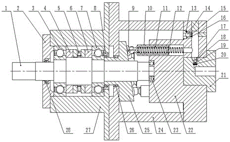
[0026] Such as figure 1 As shown, a swash plate rotary type internal valve distribution axial piston pump of the present invention includes a front end cover 2, a front pump body 27, a pump shaft arranged in the front pump body 27, and a bearing installed on the pump shaft 1. Components, sealing components, rear pump body 24, swash plate 25 installed in rear pump body 24, plunger shoe assembly, return spring 12, cylinder block 22, suction valve assembly installed in cylinder block 22, rear end cover 21. And an extrusion valve set installed in the rear end cover 21; wherein the front end cover 2, the front pump body 27, the rear pump body 24, the cylinder 22 and the rear end cover 21 are fixedly connected in sequence; the plunger The shoe assembly is placed in the plunger hole inside the cylinder 22; the swash plate 25 is connected to the pump shaft 1 through splines, so that the sw...
PUM
Abstract
The invention discloses an inclined-disc-rotating internally-disposed valve flow distribution axial plunger pump which comprises a front end cap, a front pump body, a pump shaft, a bearing component, a sealing component, a rear pump body, an inclined disc, a plunger sliding shoe component, a return spring, a cylinder body, a suction valve set, a rear end cap and an extrusion valve set. The pump shaft is arranged in the front pump body, the bearing component is mounted in the pump shaft, the inclined disc is mounted in the rear pump body, the suction valve set is mounted in the cylinder body, the extrusion valve set is mounted in the rear end cap, the pump shaft drives the inclined disc to rotate through a spline and jointly bears axial force and radial force of the inclined disc through a thrust bearing and a deep groove ball bearing, the cylinder body is fixed on the rear pump body and is relatively static, and the suction valve set and the extrusion valve set are mounted at the tail of the cylinder body and the rear end cap respectively. The inclined-disc-rotating internally-disposed valve flow distribution axial plunger pump is simple in structure, convenient to maintain, higher in specific power and performance-cost ratio, high in anti-fouling performance and especially suitable for high-pressure water pumps, leakage of the plunger pump is reduced effectively, and working pressure and volume efficiency are improved.
Description
Technical field [0001] The invention relates to the field of hydraulic pumps, in particular to an axial plunger pump with a swash plate rotation type built-in valve distribution valve. Background technique [0002] With the development of hydraulic pumps in the direction of high speed, high pressure and energy saving, the research on axial piston pumps has become more and more extensive. The axial piston pump has the advantages of compact structure, small unit power volume, light weight, higher pressure than other hydraulic pumps, and long life. However, the disadvantages are sensitivity to oil pollution, high requirements for oil filtering accuracy, and high cost. The existing researches on axial piston pumps are mainly divided into three types: end flow distribution, valve flow distribution and shaft flow distribution. The end face distribution relies on the valve plate to separate the high pressure cavity and the low pressure cavity. Both the end face distribution and the sha...
Claims
Application Information
Patent Timeline
Application Date:The date an application was filed.
Publication Date:The date a patent or application was officially published.
First Publication Date:The earliest publication date of a patent with the same application number.
Issue Date:Publication date of the patent grant document.
PCT Entry Date:The Entry date of PCT National Phase.
Estimated Expiry Date:The statutory expiry date of a patent right according to the Patent Law, and it is the longest term of protection that the patent right can achieve without the termination of the patent right due to other reasons(Term extension factor has been taken into account ).
Invalid Date:Actual expiry date is based on effective date or publication date of legal transaction data of invalid patent.