Sealing ring for centrifugal pump

A sealing ring and centrifugal pump technology, applied in the field of centrifugal pump sealing ring, can solve the problems of uneven flow change of double-suction centrifugal pump, reducing the inlet pressure of impeller, affecting the hydraulic performance of the unit, etc., so as to avoid hydraulic loss, reduce vortex and cost. low effect

Inactive Publication Date: 2007-01-31
SHANGHAI KAIQUAN PUMP IND GROUP
View PDF0 Cites 2 Cited by
  • Summary
  • Abstract
  • Description
  • Claims
  • Application Information

AI Technical Summary

Problems solved by technology

In this way, the flow rate of the double-suction centrifugal pump will vary unevenly during the working process, and the vibration of the unit will increase.
When the flow rate is lower than the design flow rate of the pump to a certain extent, there will be secondary backflow at the impeller inlet. This backflow not only brings additional hydraulic loss, but also worsens the cavitation condition of the pump: the backflow area occupies the effective area of ​​the impeller inlet, and the water flow When the impeller inlet velocity increases, the flow velocity distribution is disordered. In addition, the hydraulic loss in the backflow vortex area will reduce the impeller inlet pressure.
In addition, part of the high-energy liquid flows from the volute of the discharge chamber through the gap between the impeller and the sealing ring of the double-suction centrifugal pump and returns to the impeller inlet, which increases the volume loss and affects the hydraulic performance of the unit.

Method used


Image

  • Sealing ring for centrifugal pump
  • Sealing ring for centrifugal pump
  • Sealing ring for centrifugal pump

Examples


Embodiment Construction

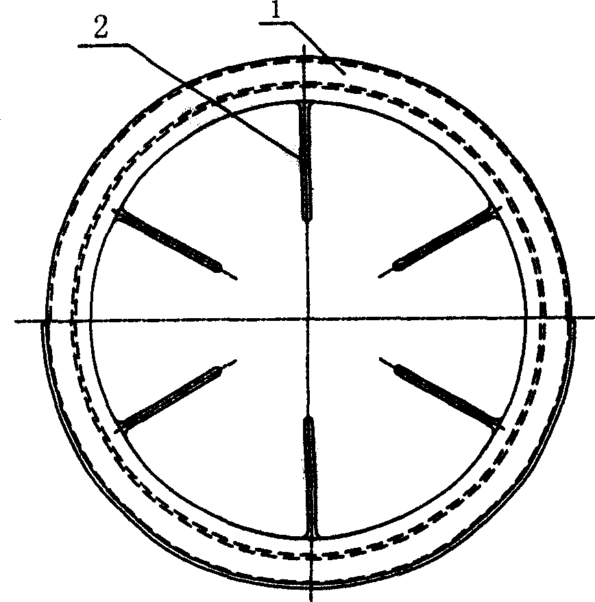
[0012] see image 3 , Figure 4 , on the inner wall 6 of the sealing ring 1, there are n pieces of rectifying grids, the number n of which is: usually 2≤n≤the number of impeller blades, and the rectifying grids at the top of the center line of the sealing ring are evenly distributed on the basis of the rectifying grids On the circumference of the inner wall 6 (note: a large number of rectifying grids will increase the friction loss of the pump under the condition of large flow rate). The width, thickness, length and transition radius of its rectifying grid sheet 2 can be determined according to specific conditions.

[0013] see Figure 5 , is a schematic diagram of the joint use of the seal ring and the impeller of the present invention, and a labyrinth seal groove 4 is provided at the straight opening of the joint portion of the seal ring 1 and the impeller 5 . This technique is relatively clear to those skilled in the art.


PUM


Abstract

The invention relates a sealing ring for a centrifugal pump, on whose inner wall is uniformly distributed at least more than two commutator bars. The number of the commutator bars is less than or equal to the number of the impeller vanes. In the open-entry position of fitting the sealing ring with the impeller is opened a sealed groove.

Description

[technical field] [0001] The invention relates to the technical field of sealing rings of centrifugal pumps, in particular to a sealing ring for double-suction centrifugal pumps. [Background technique] [0002] see figure 1 , for the existing double-suction centrifugal pump sealing ring (also known as the mouth ring). Generally speaking, the sealing ring of the double-suction centrifugal pump uses a wide flow channel in the inner cavity to supply the pumped liquid to pass through. Since the pumped liquid has the inertia of maintaining the original state, the liquid cannot enter the impeller completely smoothly and evenly. When liquids with different energies enter the impeller, they will collide with each other to achieve energy balance. In the process of mutual impact, the greater the energy gap of the liquid, the greater the impact loss. In this way, the flow rate of the double-suction centrifugal pump will vary unevenly during the working process, and the vibration of ...

Claims


Application Information

Patent Timeline
IPC IPC(8): F04D29/08
Inventor 邓帮华
Owner SHANGHAI KAIQUAN PUMP IND GROUP
Why Eureka
Try Eureka