Reciprocating propeller

A technology of reciprocating swing and propeller shaft, which is applied in the direction of propellers, rotorcraft, non-rotating propulsion elements, etc., and can solve problems such as technical difficulties

Inactive Publication Date: 2007-01-31
邵跃波 +1
View PDF0 Cites 1 Cited by
  • Summary
  • Abstract
  • Description
  • Claims
  • Application Information

AI Technical Summary

Problems solved by technology

[0003] Flapping-wing flight is a kind of flight driven by wings (or a reciprocating propeller), but it is generally believed that it is technically difficult to realize manned aircraft flying in the way of flapping wings ("100 Years of World Aircraft" , Tan Zhaowu, Shen Meizhen, Meng Queming, National Defense Industry Press, 2003)

Method used


Image

  • Reciprocating propeller
  • Reciprocating propeller
  • Reciprocating propeller

Examples


Embodiment Construction

[0102] Embodiment: replace common propeller with reciprocating propeller to drive fixed-wing light aircraft, namely " reciprocating propeller aircraft ".

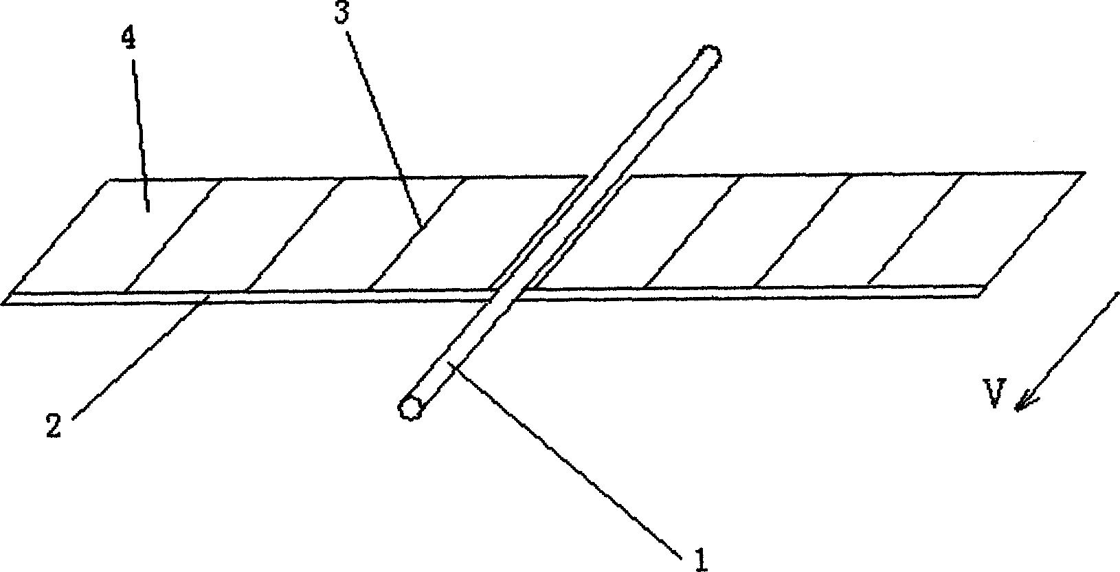
[0103] A reciprocating propeller with a single shaft and two blades is used, and it is placed on the head of the aircraft or the top of the aircraft like a common propeller. When placed on the top of the aircraft, care should be taken not to conflict with the fixed wing.

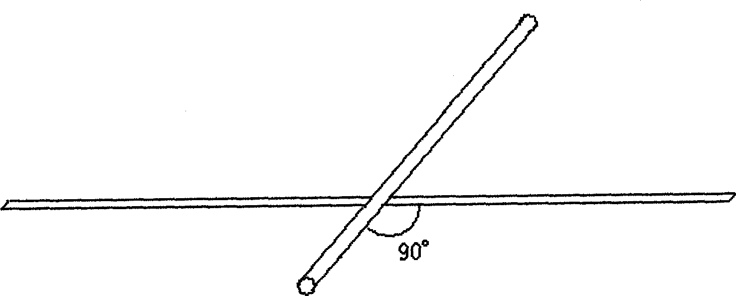
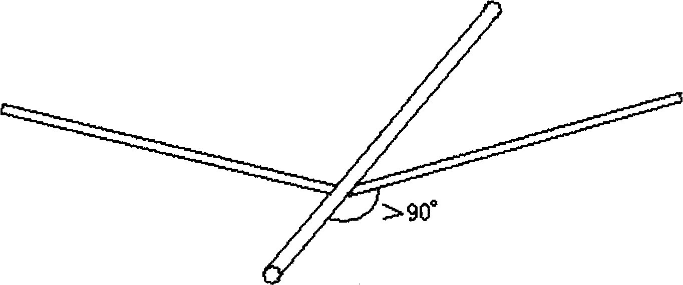
[0104] Since the driving direction of the reciprocating propeller coincides with the propeller shaft of the reciprocating propeller, the angle between the axis of the propeller shaft and the plane of the fixed wing of the aircraft must be carefully determined.

[0105]Using chain transmission and chain deceleration, the rotational motion of the engine is converted into the symmetrical reciprocating rotation of the paddle shaft through the crank rocker mechanism (that is, the reciprocating and reciprocating rotations are completely symmetrical); the paddle ...


PUM


Abstract

There is disclosed a reciprocating propeller, in which a propeller-blade is made up of a propeller rod, propeller ribs and a propeller surface made of elastic material, so it can oscillate back and forth in the range less than or equal to 180 deg. By the action of the propeller surface torsion and whipping of the propeller surface tip, the invention can provide driving force for airplanes and ships.

Description

technical field [0001] The invention relates to an engine-driven device for driving aircraft and ships, in particular to drive paddles or wings of the aircraft and ships. Background technique [0002] Existing various propeller planes, helicopters and motor ships all adopt the propeller for circular motion. The propeller has many advantages, but it is recognized that its driving efficiency is still far behind the flapping wings of birds and insects. [0003] Flapping wing flight is a kind of flight driven by wings (or a reciprocating propeller), but it is generally believed that it is technically difficult to realize a manned aircraft flying in the way of flapping wings ("100 Years of World Aircraft" , Tan Zhaowu, Shen Meizhen, Meng Queming, National Defense Industry Press, 2003). At present, the best manned flapping wing aircraft is a research and development team from the University of Toronto in Canada. In 1999, the full-scale prototype they made could accelerate to mor...

Claims


Application Information

Patent Timeline
IPC IPC(8): F04D33/00B64D35/00B64C11/00B64C27/32B63H1/30
Inventor 邵跃波
Owner 邵跃波
Why Eureka
Try Eureka