

Air conditioner
An air conditioner and air conditioning technology, applied in air conditioning systems, airflow control components, space heating and ventilation, etc., can solve problems such as difficulty in setting wind direction, reducing air volume, and easy condensation
- Summary
- Abstract
- Description
- Claims
- Application Information
AI Technical Summary
Problems solved by technology
Method used
Image

Examples
no. 1 Embodiment approach
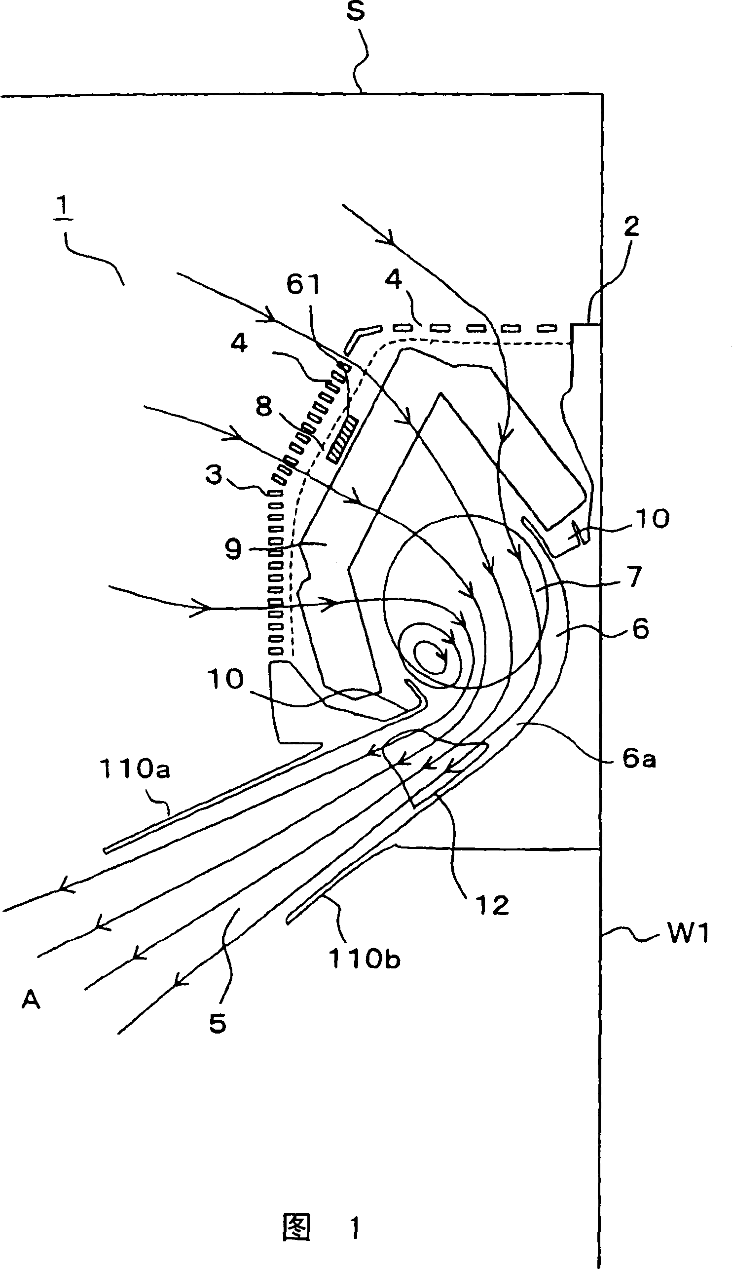
[0141] Fig. 1 is a side sectional view showing the air conditioner according to the first embodiment (showing Figure 6 D section). An indoor unit 1 of an air conditioner has a main body held by a casing 2, and a front panel 3 having a suction port 4 on the front side and a front side thereof is detachably attached to the casing 2.
[0142] The casing 2 is provided with a claw portion (not shown in the figure) on the rear side, and the claw portion cooperates with a mounting plate (not shown in the figure) installed on the side wall W1 of the living room to support the casing 2 . An outlet 5 is provided in a gap between the lower end of the front panel 3 and the lower end of the cabinet 2 . The air outlet 5 is formed in a substantially rectangular shape extending in the width direction of the indoor unit 1, and is provided facing forward and downward.
[0143] Inside the indoor unit 1 , a blower path 6 communicating from the suction port 4 to the blower port 5 is formed. A ...
no. 2 Embodiment approach
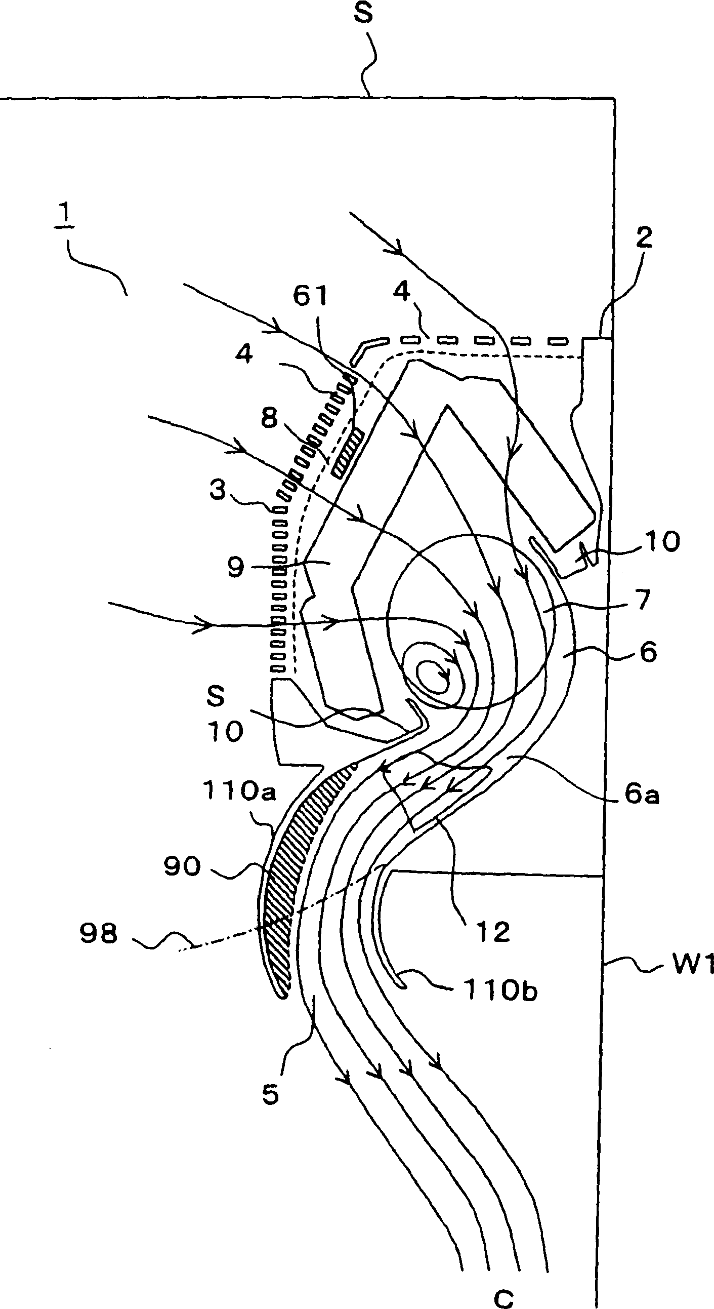
[0182] Next, Fig. 9 is a side sectional view showing the air conditioner indoor unit 1 according to the second embodiment. With the above figure 1~ Figure 8 The parts that are the same as those of the first embodiment shown are denoted by the same symbols. In this embodiment, instead of the wind direction variable parts 110a and 110b made of the flexible material of the first embodiment, wind direction variable parts 111a and 111b that extend the air blowing path 6 by rotation are provided. Other parts are the same as those of the first embodiment.
[0183] The wind direction variable part 111b is rotatably supported by the rotation shaft 111d, and the wind direction variable part 111a is rotatably supported by the rotation shaft 111e via the arm part 111c connected to the rotation shaft 111d. The rotating shaft 111d is rotated by being driven by a drive motor 111f through a gear (not shown). In addition, a position restricting portion 111g for restricting the position of ...
no. 3 Embodiment approach
[0194] then, Figure 12 It is a side sectional view which shows the air conditioner indoor unit 1 which concerns on 3rd Embodiment. With the above figure 9~ Figure 11 The same parts of the second embodiment shown are denoted by the same symbols. In this embodiment, instead of the wind direction variable parts 111a and 111b of the second embodiment, wind direction variable parts 112a and 112b which can be rotatably supported are provided. Other parts are the same as the second embodiment.
[0195] The wind direction variable part 112b extends the lower wall of the front guide part 6, and the rotating shaft 112f driven by the drive motor (not shown) is pivotally supported on the casing 2. An upper arm 112c is rotatably connected to the rotation shaft 112f, and the upper arm 112c is rotatably connected to the lower arm 112d via an arm joint 112e. The wind direction variable part 112a (first wind direction plate) is rotatably supported on the lower arm part 112d by a rotating s...
PUM
 Abstract
Description
Claims
Application Information