Front projection type multi-projection display

A multi-projection and display technology, applied in instruments, televisions, optics, etc., to achieve the effect of shortened adjustment time and easy setting

Inactive Publication Date: 2007-01-31
SEIKO EPSON CORP
View PDF9 Cites 7 Cited by
  • Summary
  • Abstract
  • Description
  • Claims
  • Application Information

AI Technical Summary

Problems solved by technology

[0018] Therefore, the present invention was made in order to solve such a problem, and an object of the present invention is to provide a multi-projection display that enables easy adjustment work and shortens adjustment time.

Method used


Image

  • Front projection type multi-projection display
  • Front projection type multi-projection display
  • Front projection type multi-projection display

Examples


Embodiment approach 1

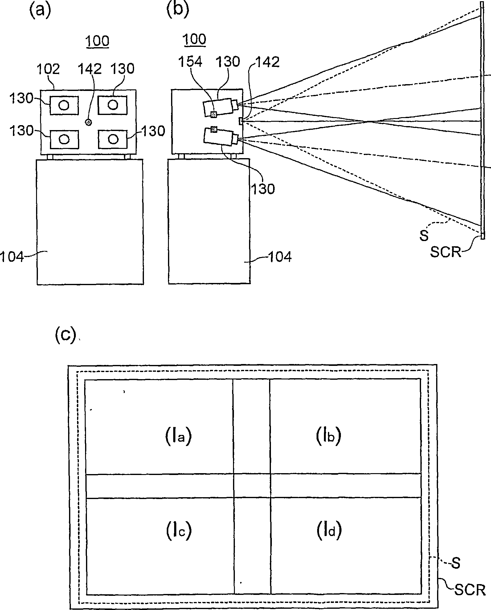
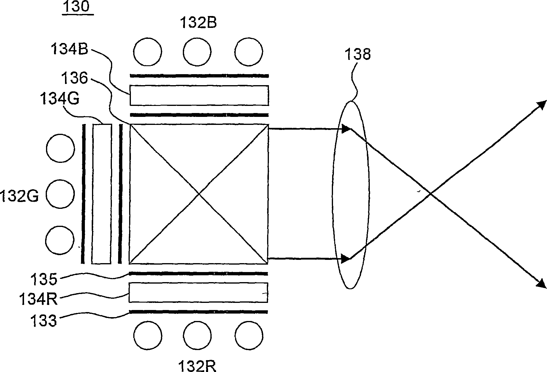
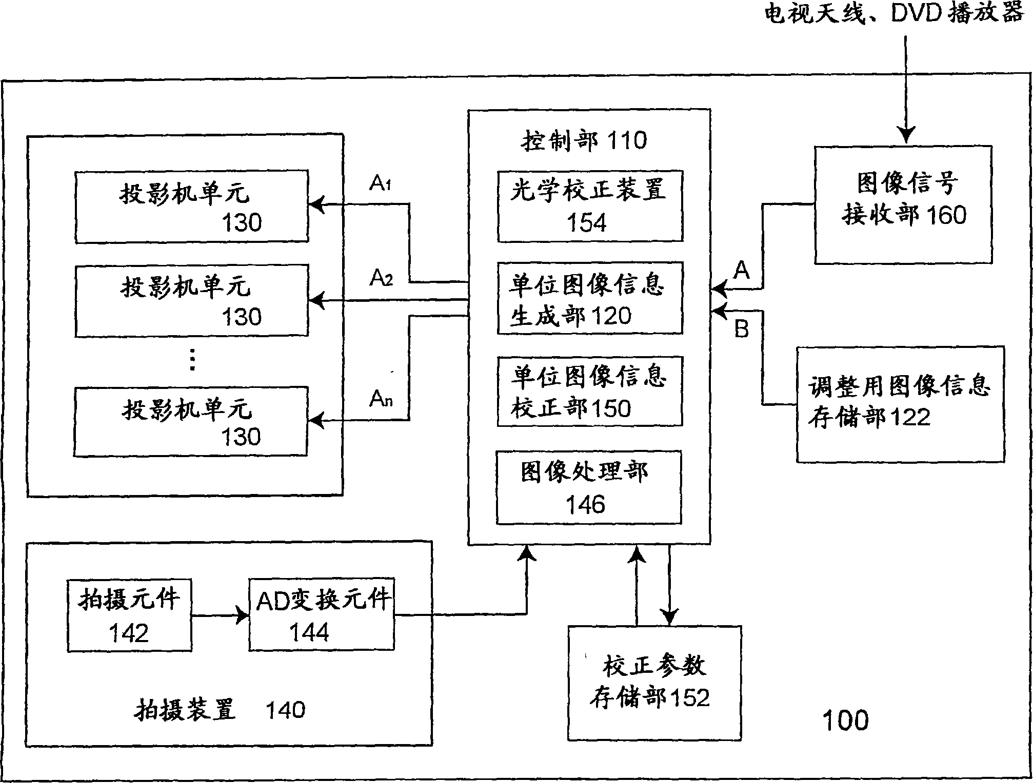
[0125] figure 1 , is a diagram showing the configuration of the front projection type multi-projection display according to the first embodiment. figure 1 (a), is the front view; figure 1 (b) is a sectional view seen from the side; figure 1 (c) is a diagram showing a projected image projected on the screen. figure 2 , is a diagram showing the configuration of the projector unit in the front projection type multi-projection display according to the first embodiment. Figure 3 ~ Figure 5 , is a block diagram showing the outline of the front projection type multi-projection display according to the first embodiment.

[0126] The front projection type multi-projection display 100 of Embodiment 1, as shown in figure 1 As shown in , it is a front projection type multi-projection display that projects projected images from four projector units 130 arranged in the housing 102 on the screen SCR as a projection surface. The front projection type multi-projection display 100, as in...

Embodiment approach 2

[0189] Figure 13 , is a diagram showing the configuration of the front projection type multi-projection display according to the second embodiment. Figure 14 , is a diagram for explaining the effect of the front projection type multi-projection display according to the second embodiment.

[0190] The front projection type multi-projection display 200 of Embodiment 2, as shown in Figure 13 As shown in , the optical axis of the projection beam from each projector unit 130 is configured to be perpendicular to the screen surface of the screen SCR.

[0191] Therefore, the unit image from each projector unit 130 has little keystone distortion. As a result, the diagram showing the effect of the front projection multi-projection display 200 according to the second embodiment is different from that shown in the front projection multi-projection display 100 according to the first embodiment. Figure 6 not the same as Figure 14 like that.

[0192] However, in the front projectio...

Embodiment approach 3

[0194] Figure 15 , is a block diagram showing the outline of the front projection type multi-projection display according to the third embodiment. Figure 16 , is a diagram for explaining the effect of the front projection type multi-projection display according to the third embodiment. Figure 16 (a) is a diagram showing the effect when the unit image has trapezoidal distortion, Figure 16 (b) is a diagram showing the effect when the unit image has no trapezoidal distortion.

[0195] The front projection type multi-projection display 300 of Embodiment 3, as in Figure 15 As shown in , the configuration of the control unit is different from that of the front projection type multi-projection display 100 according to the first embodiment. That is, the control unit 310 in the front projection multi-projection display 300 of the third embodiment has the configuration of the control unit 110 in the front projection multi-projection display 100 of the first embodiment without th...


PUM


Abstract

A front projection type multi-projection display includes a plurality of projector units to modulate and project light from a light source based on image information, an image-capturing device disposed in a housing to capture predetermined regions of the projection images projected onto the screen, a unit image information generating unit to generate image information to be input to each of the plurality of projector units, and a unit image information correcting unit to correct the unit image information based on a result captured by the image-capturing device. Therefore, it is possible to perform the adjustment process and to further reduce the adjustment time.

Description

technical field [0001] The present invention relates to a front projection type multi-projection display. Background technique [0002] A multi-projection display is known: it is capable of displaying a large screen by arranging a plurality of projector units (projection optical units) in the horizontal direction and / or vertical direction, and enlarging and projecting projected images from these plurality of projector units on a screen Image (For example, refer to Patent Documents 1 to 9.). Such a multi-projection display is expected to be used in movie theaters, art galleries, museums, discussion halls, conference halls, small theaters, and public institutions in the future because it can display high-definition and high-brightness images compared to ordinary projectors. It has been widely used in business fields such as , enterprises, etc., and in home fields such as entertainment centers and home theaters. [0003] However, in such a multi-projection display, if the pro...

Claims


Application Information

Patent Timeline
Patent Type & Authority Applications(China)
IPC IPC(8): H04N5/74G03B21/26H04N17/00
CPCH04N9/3147H04N9/3194G03B21/26G03B21/00H04N5/74G03B21/14
Inventor 宫沢康永长谷川浩
Owner SEIKO EPSON CORP
Why Eureka
Try Eureka