Operating lever type optical mouse

A technology of optical mouse and joystick, which is applied in the field of optical mouse to achieve the effects of avoiding fatigue and pain, good sensitivity, and easy production and assembly

Inactive Publication Date: 2007-02-07
NINGBO YINZHOU JIEYUAN ELECTRONICS
View PDF1 Cites 2 Cited by
  • Summary
  • Abstract
  • Description
  • Claims
  • Application Information

AI Technical Summary

Problems solved by technology

Because the positioning principle of an optical mouse is completely different from that of an electromechanical mouse, how to apply the optical positioning system in an optical mouse to a mouse that can be held vertically is still a problem. At present, there is no optical mouse that can be held vertically by the palm of the hand.

Method used


Image

  • Operating lever type optical mouse
  • Operating lever type optical mouse
  • Operating lever type optical mouse

Examples


Embodiment Construction

[0018] The present invention will be further described in detail below in conjunction with the accompanying drawings and embodiments.

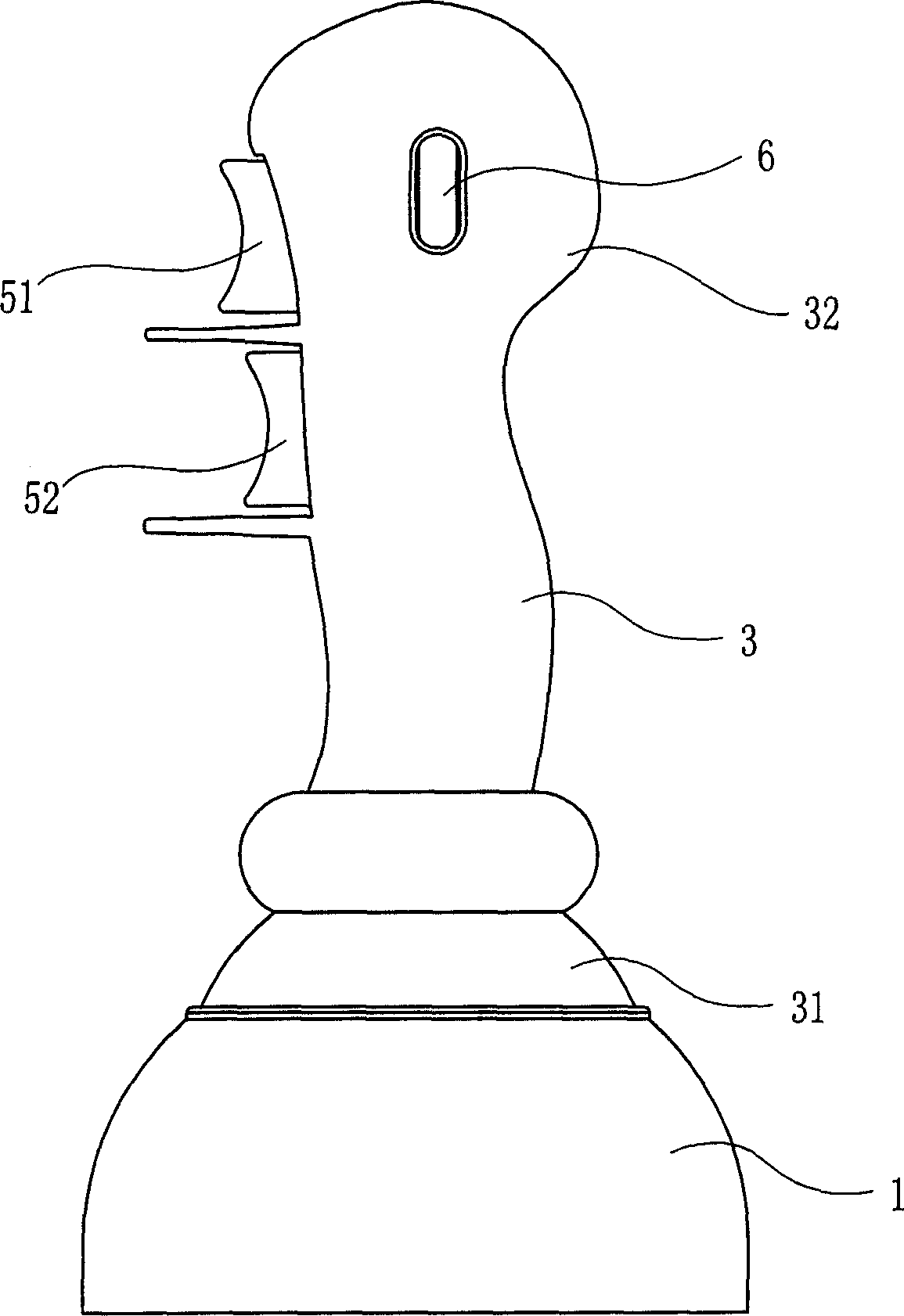
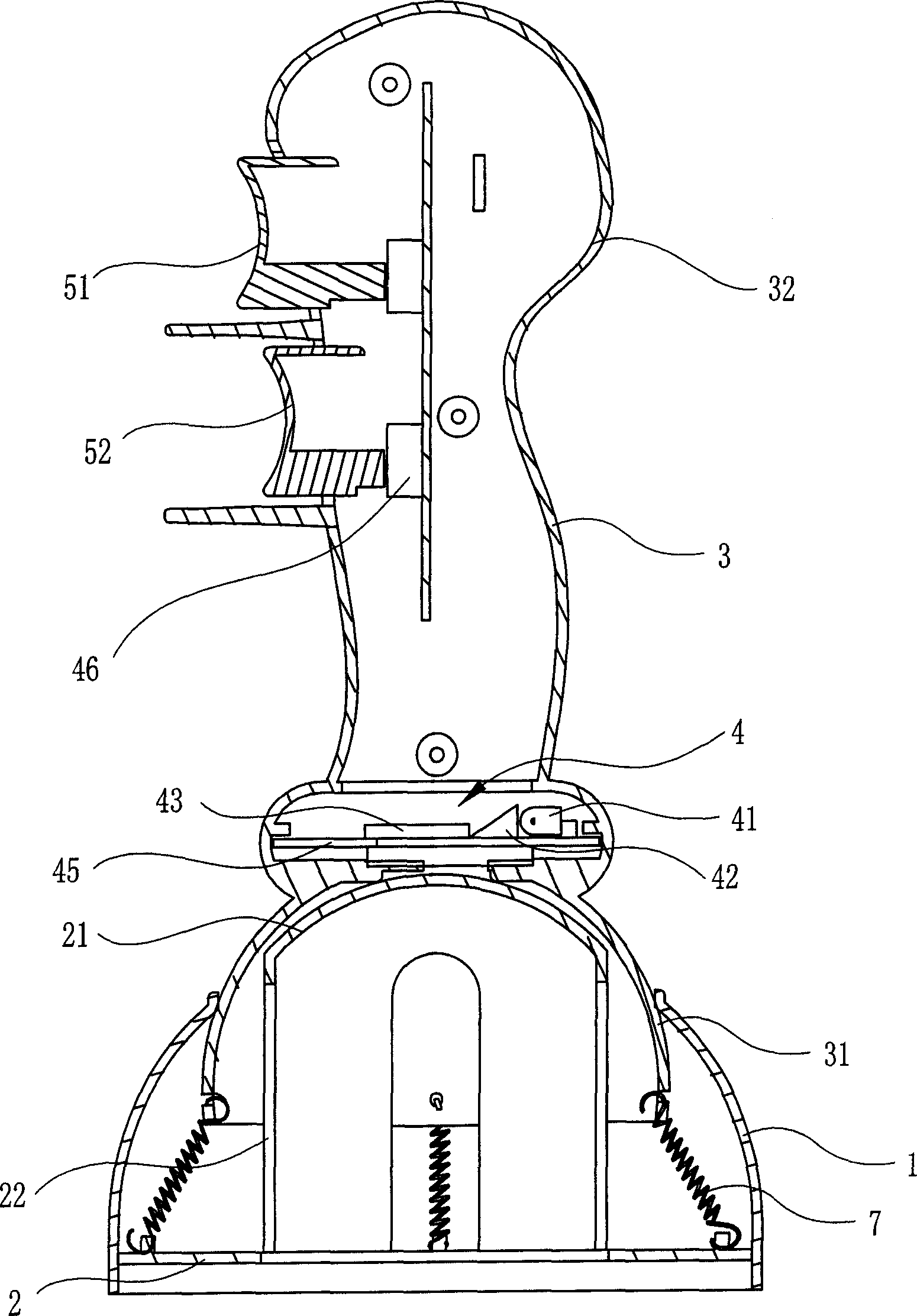
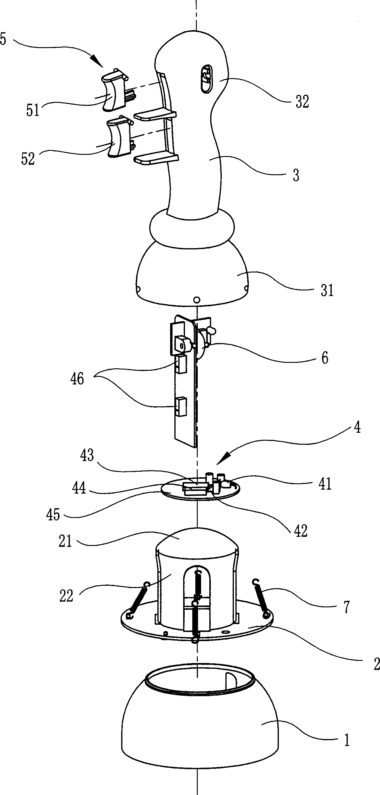
[0019] Such as Figure 1 ~ Figure 3 As shown, the joystick-type optical mouse includes a base 1, a reflection seat 2 with a spherical reflective surface 21 on the top, a joystick 3 sleeved on the reflection seat 2, and an optical positioning device set in the joystick 3. System 4 and buttons 5 and scroll wheels 6 arranged on the joystick 3;

[0020] Wherein, the optical positioning system 4 includes a light emitting diode 41, an optical lens, an optical sensor, an interface controller chip 45 and a micro switch 46, and the optical lens includes a prismatic lens 42 and a circular lens (not shown in the figure). As shown, the specific position is under the CMOS photoreceptor), and the optical sensor includes a CMOS photoreceptor 43 and a DSP processing chip 43, and the key 5 is connected with the microswitch 46 in the optical positioning system...


PUM


Abstract

The disclosed joy-stick optical mouse comprises: a base (1), a reflection base (2) with spherical reflector (21) on top, a joy stick (3) on (2), an optical positioning system (4) in (3) to irradiate the surface (21), and a press-key (5) connected with the sensitive switch (46) of (4) and a roll wheel (6) both arranged on (3). Compared with prior art, this invention is convenient and can avoid fatigue as long time operation.

Description

technical field [0001] The invention relates to an optical mouse used in computers and electronic equipment, in particular to a joystick type optical mouse. Background technique [0002] Various mice currently used on computers and electronic equipment are small in size, and most of them adapt to the shape of human hands in appearance, that is, the style design is roughly horizontal at the bottom and arched at the back. When in use, the operator's wrist joint is generally Prone against the desktop, while the palm of the hand lies prone on the back of the mouse, and roughly coincides with the back, and the fingers are distributed on the back of the mouse in their respective positions. In this way, the operator's wrist tends to bend upwards, and the wrist will naturally It bears greater pressure, especially when the mouse moves on a flat surface. Such a long-term use will damage the muscles and meridians of the hand, and will also cause soreness and fatigue in the operator's a...

Claims


Application Information

Patent Timeline
Patent Type & Authority Applications(China)
IPC IPC(8): G06F3/033G05G9/047G06F3/0354
Inventor 王绪杰
Owner NINGBO YINZHOU JIEYUAN ELECTRONICS
Why Eureka
Try Eureka