Electronic blood pressure monitor
An electronic sphygmomanometer and blood pressure technology, applied in vascular assessment, cardiac catheterization, etc., can solve problems such as poor operability and achieve the effect of preventing misoperation
- Summary
- Abstract
- Description
- Claims
- Application Information
AI Technical Summary
Problems solved by technology
Method used
Image
Examples
Embodiment approach 1
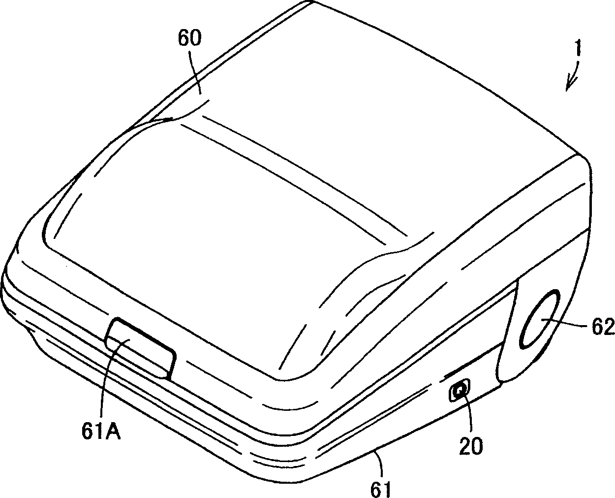
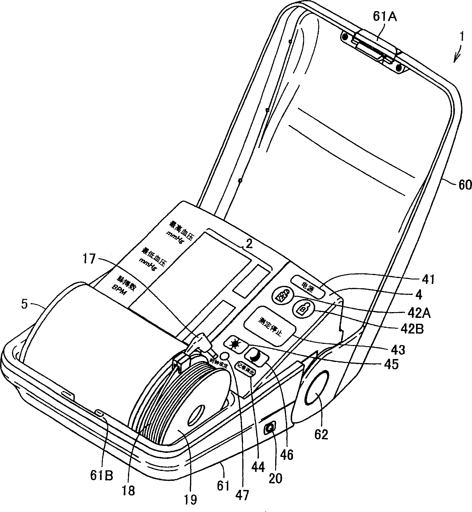
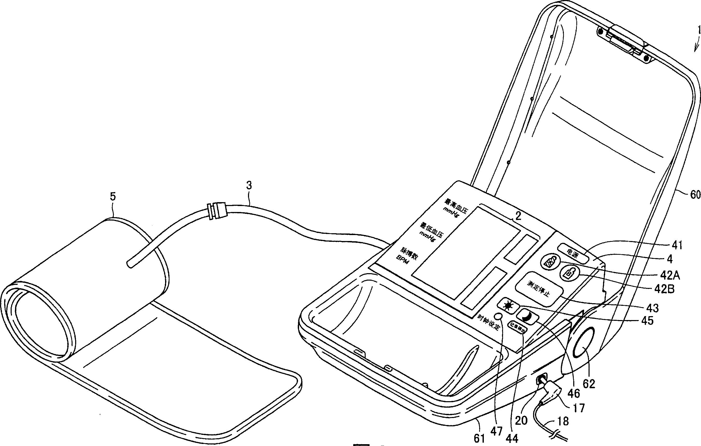
[0057] In Embodiment 1, when the front cover 60 is opened, the operation sequence for notifying the switches to be operated starts.
[0058] refer to Figure 4 , the electronic sphygmomanometer 1 according to Embodiment 1 has: a cuff 5, which is used to be worn on the blood pressure measurement site (upper arm) of the subject and pressurized by air pressure; an air tube 3, which is connected to the main body 61 and cuff 5. exist Figure 4 In the drawing, the right side of the drawing shows each part corresponding to the main body 61 with the air pressure joint 31 as a boundary. The main body 61 has a display unit 2 provided so that the subject can confirm the displayed content, and an operation unit 4 provided so that the subject can operate from the outside. Here, the measurement portion is set to the upper arm, but it is not limited thereto, and may be the wrist or fingers.
[0059] The main body 61 has: a pressure sensor 7 for outputting, as a pulse signal, a change in ...
Embodiment approach 2
[0099] exist Figure 7 The functional structure of the electronic sphygmomanometer 1 according to the second embodiment is shown. and Figure 4 Compared with the illustrated functional configuration, the difference is that a control unit 16A is provided instead of the control unit 16 , and a switch 22 for detecting connection of the cuff 5 is provided instead of the switch 21 for detecting opening and closing of the front cover 61 . The control unit 16A has a connection determination unit 168 instead of the opening and closing determination unit 167 . Other parts of the electronic sphygmomanometer 1 are the same as those of the first embodiment. Like the opening / closing determination unit 167 , the connection determination unit 168 has a function of a start detection unit that detects the timing of the start of the operation accompanying the guidance of the operation procedure.
[0100] The cuff 5 is detachably connected to the main body 61 via the pneumatic joint 31 . The...
Embodiment approach 3
[0108] exist Figure 11 The structure of the electronic sphygmomanometer 1 according to Embodiment 3 is shown. Figure 11 structure and Figure 4 Compared with the structure of the above, the difference is that a control unit 16B is provided instead of the control unit 16, and a switch 23 for detecting cuff wrapping is provided inside the cuff 5 instead of the switch 21 for detecting opening and closing of the front cover 60 . The control unit 16B includes a entanglement determination unit 169 instead of the opening and closing determination unit 167 of the control unit 16 , but other parts are the same as the control unit 16 . Like the opening / closing determination unit 167, the entanglement determination unit 169 has a function of a start detection unit that detects the timing at which the operation accompanying the guidance of the operation sequence starts.
[0109] like Figure 13 As shown, the switch 23 for detecting that the cuff 5 is wrapped around the measurement si...
PUM
 Abstract
Description
Claims
Application Information
 - R&D
- Intellectual Property
- Life Sciences
- Materials
- Tech Scout
- Unparalleled Data Quality
- Higher Quality Content
- 60% Fewer Hallucinations
Browse by: Latest US Patents, China's latest patents, Technical Efficacy Thesaurus, Application Domain, Technology Topic, Popular Technical Reports.
© 2025 PatSnap. All rights reserved.Legal|Privacy policy|Modern Slavery Act Transparency Statement|Sitemap|About US| Contact US: help@patsnap.com


