Adjustable downlight fitting

An adjustable, lighting technology that is applied to lighting devices, components of lighting devices, lighting auxiliary devices, etc., and can solve problems such as blocking light beams

Inactive Publication Date: 2007-02-14
RADIANT LIGHTING
View PDF0 Cites 5 Cited by
  • Summary
  • Abstract
  • Description
  • Claims
  • Application Information

AI Technical Summary

Problems solved by technology

The pivot axis also causes the rotational movement to

Method used


Image

  • Adjustable downlight fitting
  • Adjustable downlight fitting
  • Adjustable downlight fitting

Examples


Embodiment Construction

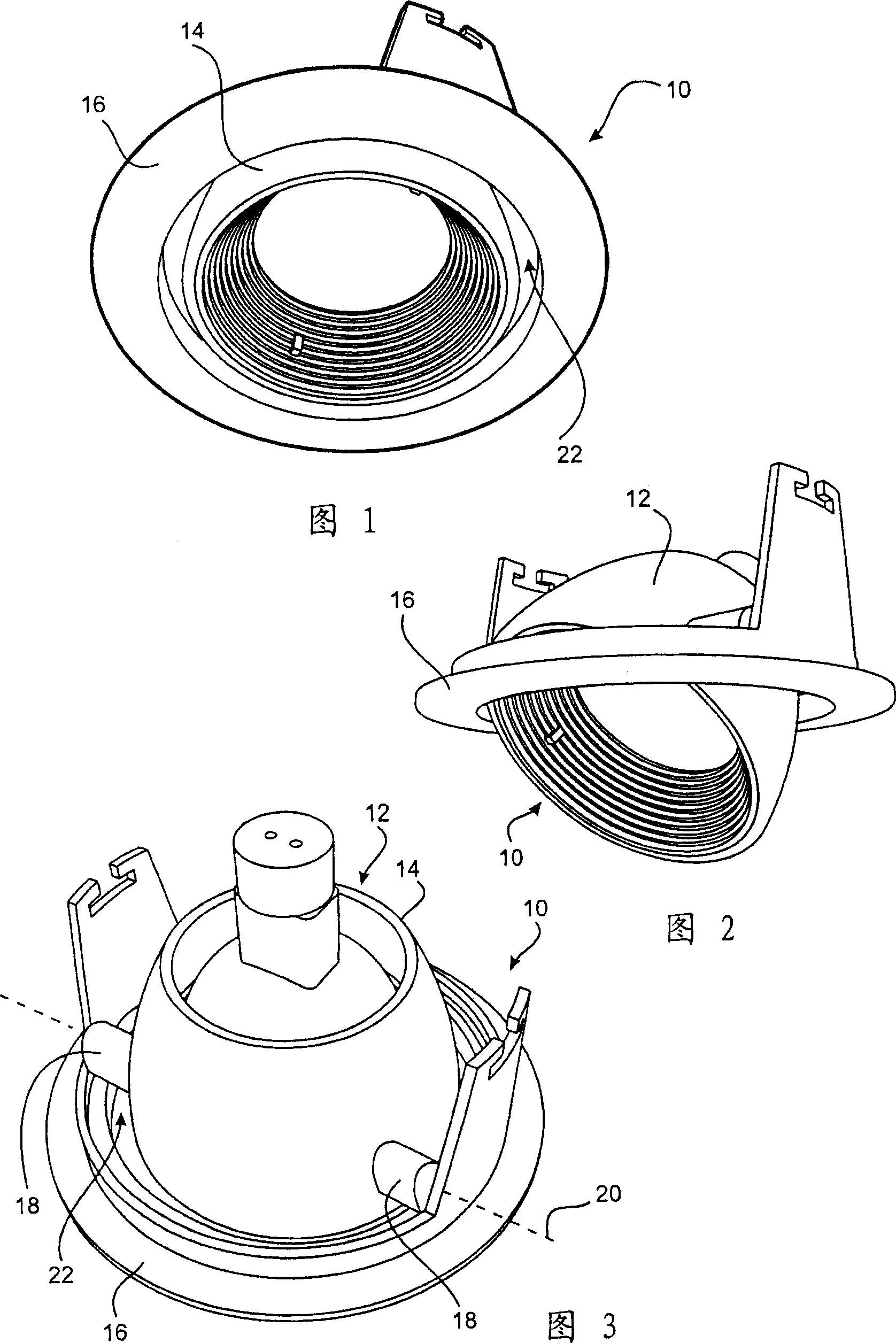
[0025] 1-3 illustrate a prior art downlight luminaire 10 of the type described above in the background section. The bulb holder 12 has a symmetrically rotatable housing 14 attached to a mounting bezel 16 by a pair of simple brackets 18 which allow rotation of the bulb holder about an axis 20 defined by fixed rivets. As mentioned above, the pivot axis 20 is positioned behind the mounting bezel 16 in order to conceal the pivot bracket 18 . In order for the bulb holder 12 to be able to rotate, there must be a substantially annular gap 22 between the bulb holder 12 and the mounting bezel 16 . The gap 22 allows the entry of dirt and debris from within the roof cavity. The pivot axis also causes the rotational movement to partially block the light beam in the rotated position as shown in FIG. 2 . Additionally, as noted above, under repeated motion conditions, the frictional forces of the rivet fasteners used to secure the pivot bracket 18 tend to decrease over time and result in i...


PUM


Abstract

A downlight luminaire(30)which can be installed to the roof in an embedding fashion comprises an installation frame(32)for installing the downlight luminaire to the roof and an adjustable outer gate barrel(34)which is coupled to the inner side of the installation frame(32)and has a casing with a curving external surface(36), and the radius of curvature of the external surface(36)is basically equal to the width of the outer gate barrel(34). The adjustable downlight luminaire comprises a pressing element(38)installed, approaching to the external surface(36), to the installation frame(32)in a manner of a compressibile roller(42). The compressibile roller(42)is adjusted to press on the external surface(36)so as to apply pressure to the outer gate barrel(34)without reference to the position of the outer gate barrel(34). In such a way, in using, the outer gate barrel(34)can be pivoted to the expectant angle with respected to the pivoting point(40)arranged on one side of the outer gate barrel(34)opposite to the compressibile roller(42), and can be kept at the angle by the compressibile roller(42).

Description

technical field [0001] The invention relates to an adjustable down-lighting lamp for embedded installation on the roof. Background technique [0002] Many home and office environments are now incorporating downlight fixtures to provide improved lighting or create a special ambiance not possible with traditional fluorescent or incandescent lighting. Flush-mounted roof downlight fixtures using 12-volt halogen bulbs are very common. There are many existing examples of 12 volt downlight fixtures that include mechanisms to turn and tilt the bulb holder so that the axis of light can be moved. When the overall size of the luminaire is large relative to the bulb, a gimbal mount or similar mount is used. [0003] If the overall size of the luminaire is relatively compact relative to the size of the bulb, there will be no room for elaborate mounting mechanisms such as gimbals. In this case, alternative downlight mounting structures already exist in the prior art. In one example, t...

Claims


Application Information

Patent Timeline
IPC IPC(8): F21V21/14
Inventor 唐纳德·J·厄恩肖迈克尔·狄克逊
Owner RADIANT LIGHTING
Why Eureka
Try Eureka