Elevator traction machine

A technology of elevator traction machine, cover, applied in the direction of elevators, elevators, transportation and packaging in buildings, which can solve the problems of difficulty in operating elevators quietly, weakening, and increased production costs

Inactive Publication Date: 2007-02-14
许宰勇 +1
View PDF0 Cites 7 Cited by
  • Summary
  • Abstract
  • Description
  • Claims
  • Application Information

AI Technical Summary

Problems solved by technology

At this time, noise and vibration occur periodically, making it difficult to operate the elevator quietly
In addition, the pin 223 also has the problem of being weakened due to periodic impacts generated by the contact of the cycloidal gears 211 and 213 with the pin wheel 222.
In addition, since it is difficult to manufacture the cycloidal gears 211 and 213 using general-purpose gear manufacturing equipment, there is a problem of increased production cost

Method used


Image

  • Elevator traction machine
  • Elevator traction machine
  • Elevator traction machine

Examples


Embodiment Construction

[0030] Next, preferred embodiments of the present invention will be described in detail with reference to the accompanying drawings.

[0031] In order to easily understand the following description of the construction and embodiments of the elevator traction machine according to the present invention, the side or end where the drive motor is located is defined as "one side or one end", and the other side or end where the end cover is connected is defined as "one side or one end" Defined as "the other side or end".

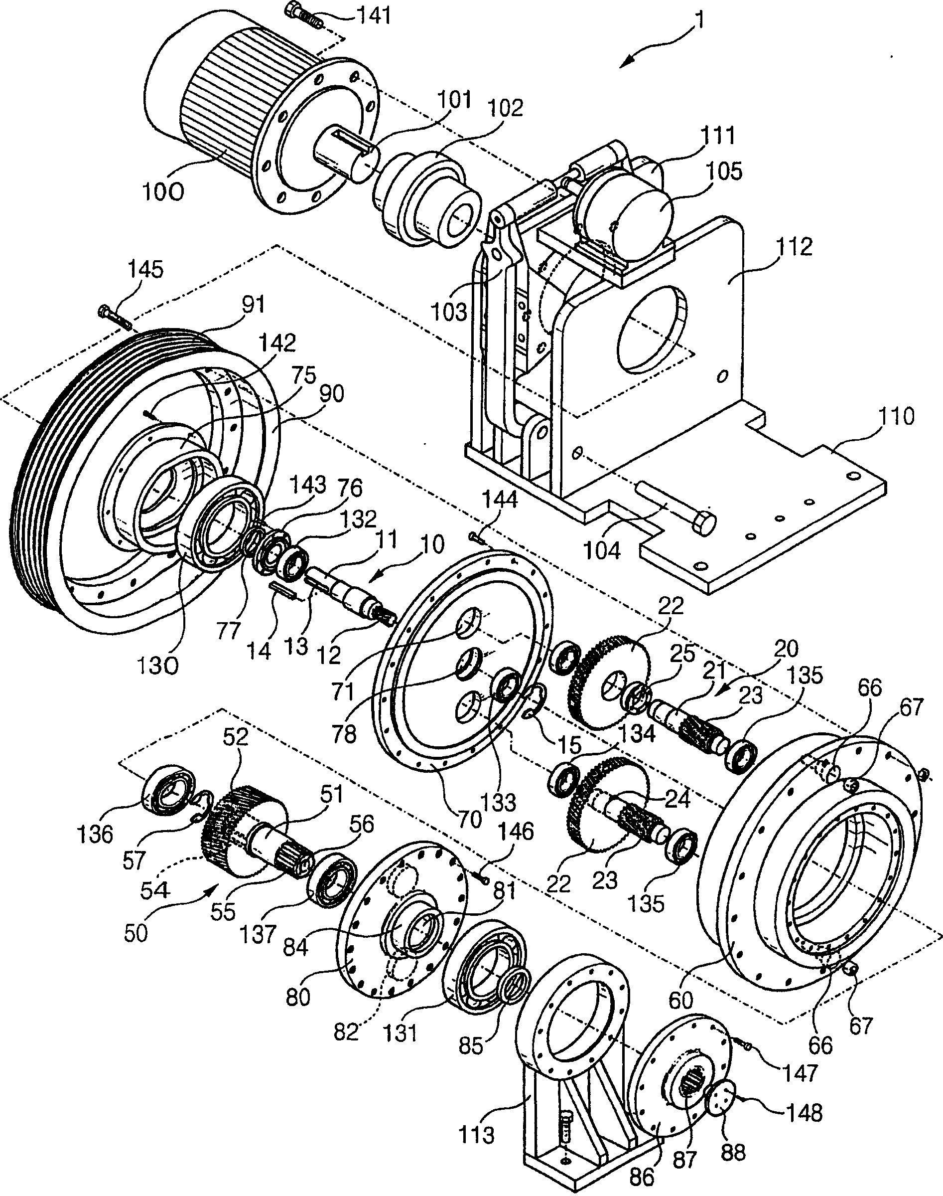
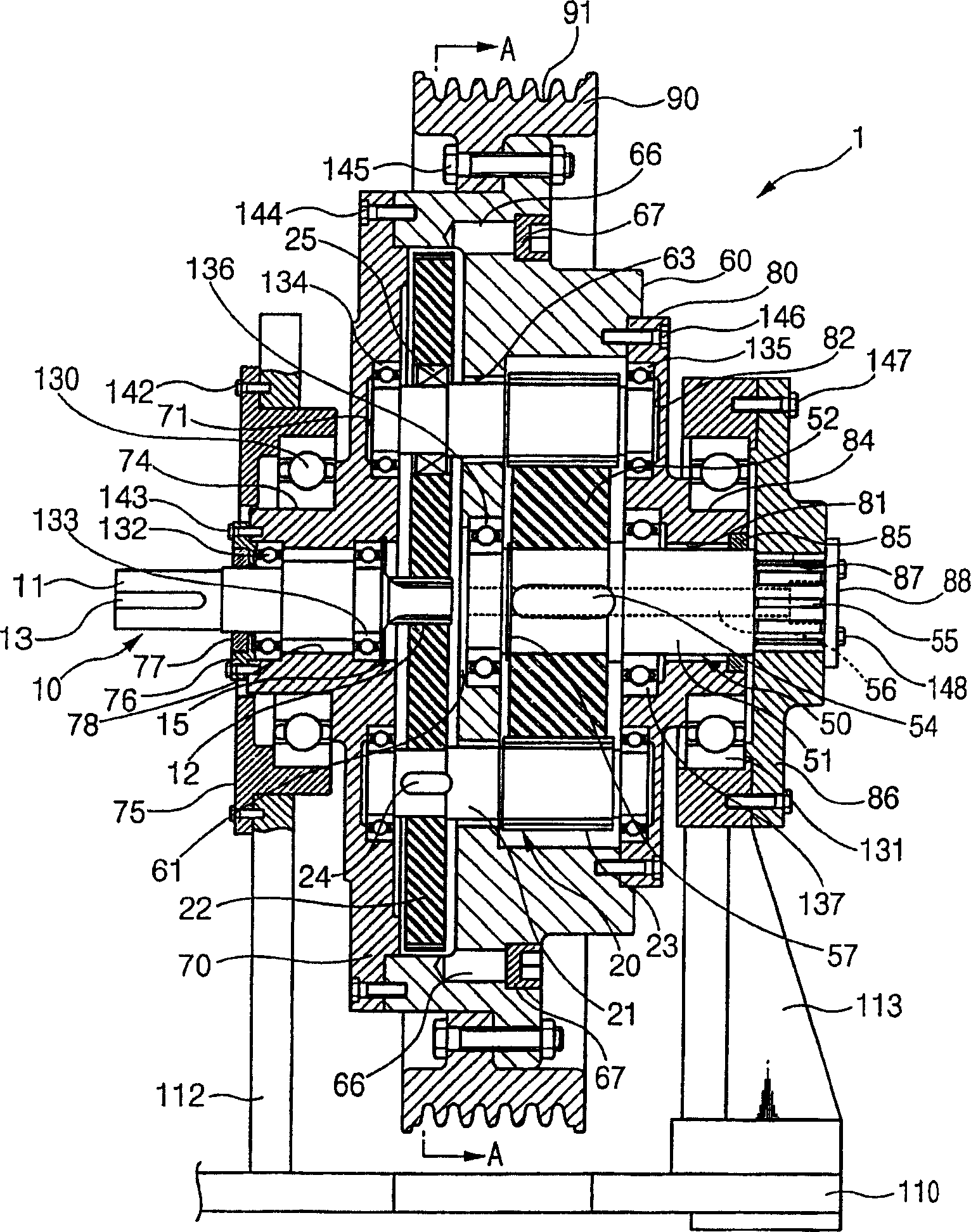
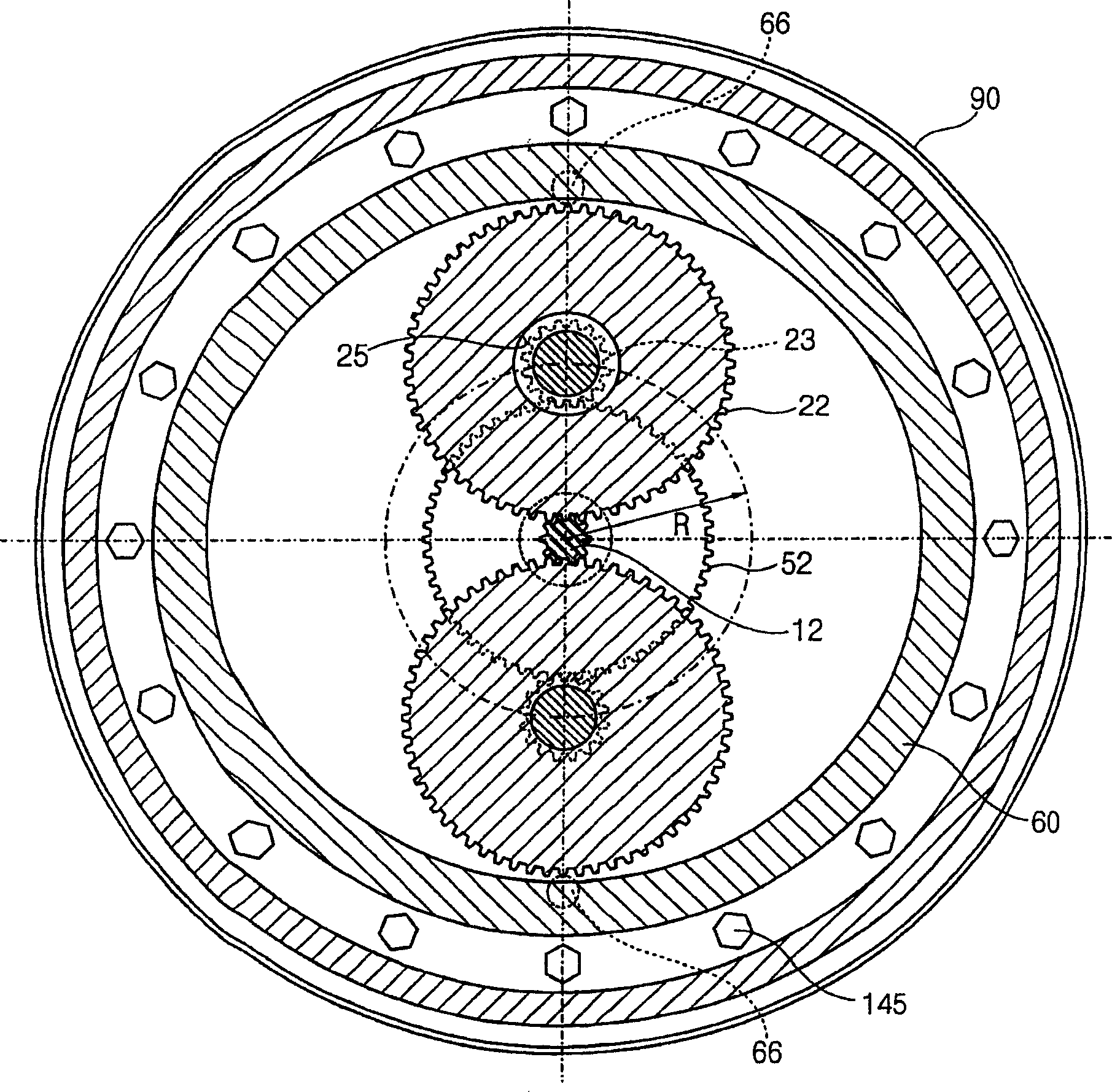
[0032] Figures 1 to 4 They are an exploded perspective view, a sectional view showing an assembled state, a sectional view showing a gear meshing state, and a front view of the elevator traction machine according to the first embodiment of the present invention, respectively.

[0033] The elevator traction machine 1 according to the first embodiment of the present invention includes a driving device, a braking device, a decelerating device, a rotating device, a s...


PUM


Abstract

The present invention relates to an elevator traction machine, and more particularly, to an elevator traction machine, wherein a plurality of planetary gears are coupled to be circumscribed and engaged with a sun gear formed at one end of a driven shaft in order to reduce high speed rotation transmitted from a driving motor and to wind wires on a sheave, and pinions formed at the other sides of the planetary gears are circumscribed and engaged with a plurality of other planetary gears or a fixed sun gear so that planetary gears just before the fixed sun gear can be rotated together with a flange, thereby obtaining reduction effects for a gear ratio among the sun gears, pinions and planetary gears, and noise / vibration-reducing effects and large rotational force-transmitting effects due to formation of the gears out of helical gears.

Description

technical field [0001] The present invention relates to elevator traction machines, and more particularly, to elevator traction machines in which a plurality of planetary gears are connected to circumscribe and mesh with a sun gear formed at one end of a driven shaft, thereby reducing The high-speed rotation transmitted by the motor and winds the rope on the sheave, and on the other side of the planetary gear forms a pinion that circumscribes and meshes with multiple other planetary gears or a fixed sun gear, so that the planetary gear just before the fixed sun gear It can rotate together with the flange, thereby obtaining the effect of reducing the transmission ratio between the sun gear, the pinion gear and the planetary gear, the effect of reducing noise / vibration, and the effect of obtaining a large rotational force transmission due to the gear construction of the helical gear. Background technique [0002] Usually, the elevator is provided with a traction machine on the...

Claims


Application Information

Patent Timeline
Patent Type & Authority Applications(China)
IPC IPC(8): B66B11/04
CPCB66B11/0453B66B5/18
Inventor 许宰勇百乐川
Owner 许宰勇
Why Eureka
Try Eureka