

Motion control device and automobile door
A technology for motion control devices and automobile doors, applied to valve devices, door/window accessories, engine components, etc., can solve the problems of slow action speed, reduced fluid resistance, complex structure, etc., and achieve stable braking characteristics and delayed closing action , to reduce the effect of strength reduction
- Summary
- Abstract
- Description
- Claims
- Application Information
AI Technical Summary
Problems solved by technology
Method used
Image

Examples
Embodiment 1
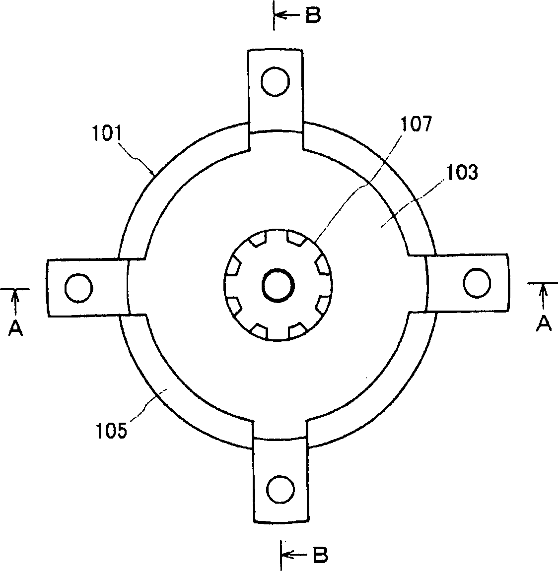
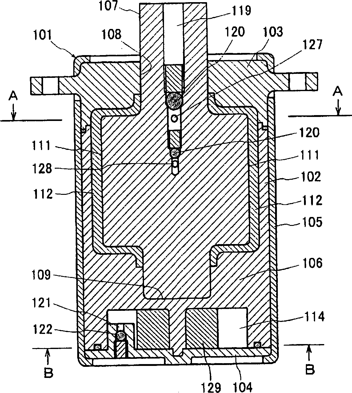
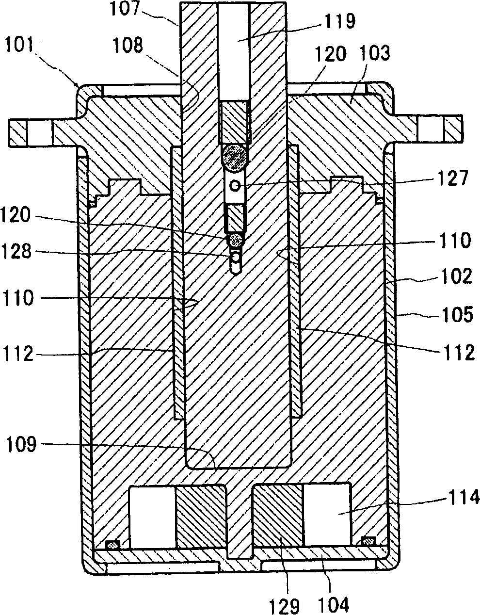
[0179] Figure 1 to Figure 7 It is a figure which shows the motion control apparatus of Example 1 of this invention. As shown in these figures, the motion control device of the present invention has: a housing 101, a shaft 107, a partition 110, a fin 111, a sealing member 112, flow paths 123-128, an accumulator 129, a fluid control mechanism 130, and a one-way Valve 134.
[0180] The casing 101 has: a main body 102, an upper cover 103, a lower cover 104, and a cover 105 (refer to figure 2 and image 3 ). The main body portion 102 has two adjacent hollow portions with the inner wall 106 interposed therebetween. The upper cover 103 is provided so as to close the opening on the one end side of the main body 102 . The lower cover 104 is provided so as to close the opening on the other end side of the main body 102 . The cover 105 is provided so as to cover the respective outer peripheral surfaces of the main body 102 , the upper cover 103 , and the lower cover 104 . Both e...
Embodiment 2
[0209] Figure 8 to Figure 10 It is a figure which shows the motion control apparatus of Example 2 of this invention. As shown in these figures, the motion control device of this embodiment has a housing 201, a shaft 205, a partition 208, a fin 209, a sealing member 210, flow paths 214, 215, and fluid control mechanisms (216, 221).
[0210] The casing 201 has a main body 202, a cover 203, and a cover 204 (see Figure 8 ). The main body portion 202 has a hollow portion opened on one end side. The cover 203 is provided so as to close the opening on the one end side of the main body 202 . The cover 204 is provided so as to cover the respective outer peripheral surfaces of the main body 202 and the cover 203 . Both ends of the covering member 204 are riveted, thereby functioning to inseparably integrate the main body portion 202 and the cover 203 with each other.
[0211] The shaft 205 is accommodated in the housing 201 so as to be relatively rotatable with respect to the hou...
Embodiment 3
[0231] Figure 11 to Figure 13 It is a figure which shows the motion control apparatus of Example 3 of this invention. As shown in these figures, the motion control device of this embodiment has a housing 301, a shaft 305, a partition 308, a fin 309, a sealing member 310, flow paths 314, 315, and fluid control mechanisms (316, 320).
[0232] The casing 310 has: a main body 302, a cover 303, and a cover 304 (refer to Figure 11 ). The main body portion 302 has a hollow portion opened on one end side. The cover 303 is provided so as to close the opening on the one end side of the main body 302 . The cover 304 is provided so as to cover the outer peripheries of the main body 302 and the cover 303 . Both ends of the covering member 304 are riveted, thereby functioning to inseparably integrate the main body portion 302 and the cover 303 with each other.
[0233] The shaft 305 is accommodated in the housing 301 so as to be relatively rotatable with respect to the housing 301 . ...
PUM
 Abstract
Description
Claims
Application Information