

Self-powered sensor
A sensor, self-powered technology, applied in the field of sensors, can solve the problems of low quality factor, reduced magnetoelectric conversion efficiency and energy output capability, large loss, etc., to improve quality factor, improve magnetoelectric voltage conversion coefficient, resonant magnetoelectric The effect of increasing conversion efficiency
- Summary
- Abstract
- Description
- Claims
- Application Information
AI Technical Summary
Problems solved by technology
Method used
Image

Examples
Embodiment 1
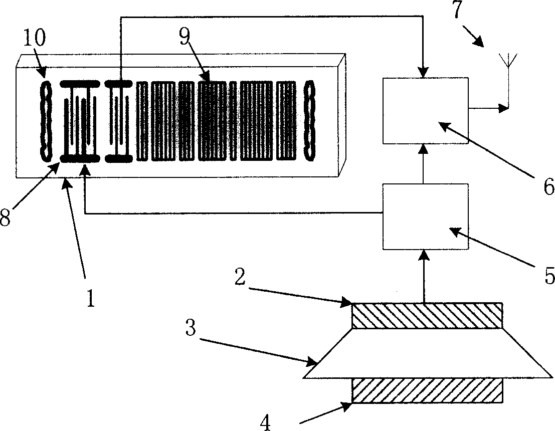
[0020] Example 1: see figure 1 , A self-powered sensor, comprising a sensor 1 and a self-powered mechanism connected through a self-powered circuit 5, characterized in that: the self-powered mechanism consists of a piezoelectric layer 2, a magnetostrictive layer 4, and a piezoelectric layer 2 and a magnetostrictive The magnifying mechanism 3 between the stretchable layers 4 is constituted. The sensor output is powered by a self-powered circuit. The transmitter circuit 6 is connected to the antenna 7 to realize wireless signal transmission.
[0021] The above-mentioned self-powered circuit 5 adopts a conventional circuit.
[0022] The aforementioned sensor 1 is a variety of surface acoustic wave sensors, usually composed of an interdigital transducer 8, a reflection grid 9 and a sound-absorbing material 10 on a piezoelectric substrate; the aforementioned amplifying mechanism 3 is a mechanical quantity amplifying mechanism, such as vibration amplifying Mechanism, force amplificatio...
Embodiment 2
[0024] Embodiment 2: It is different from Embodiment 1 in that it uses a different self-powered mechanism, more specifically, the self-powered mechanism uses a different amplifying mechanism.
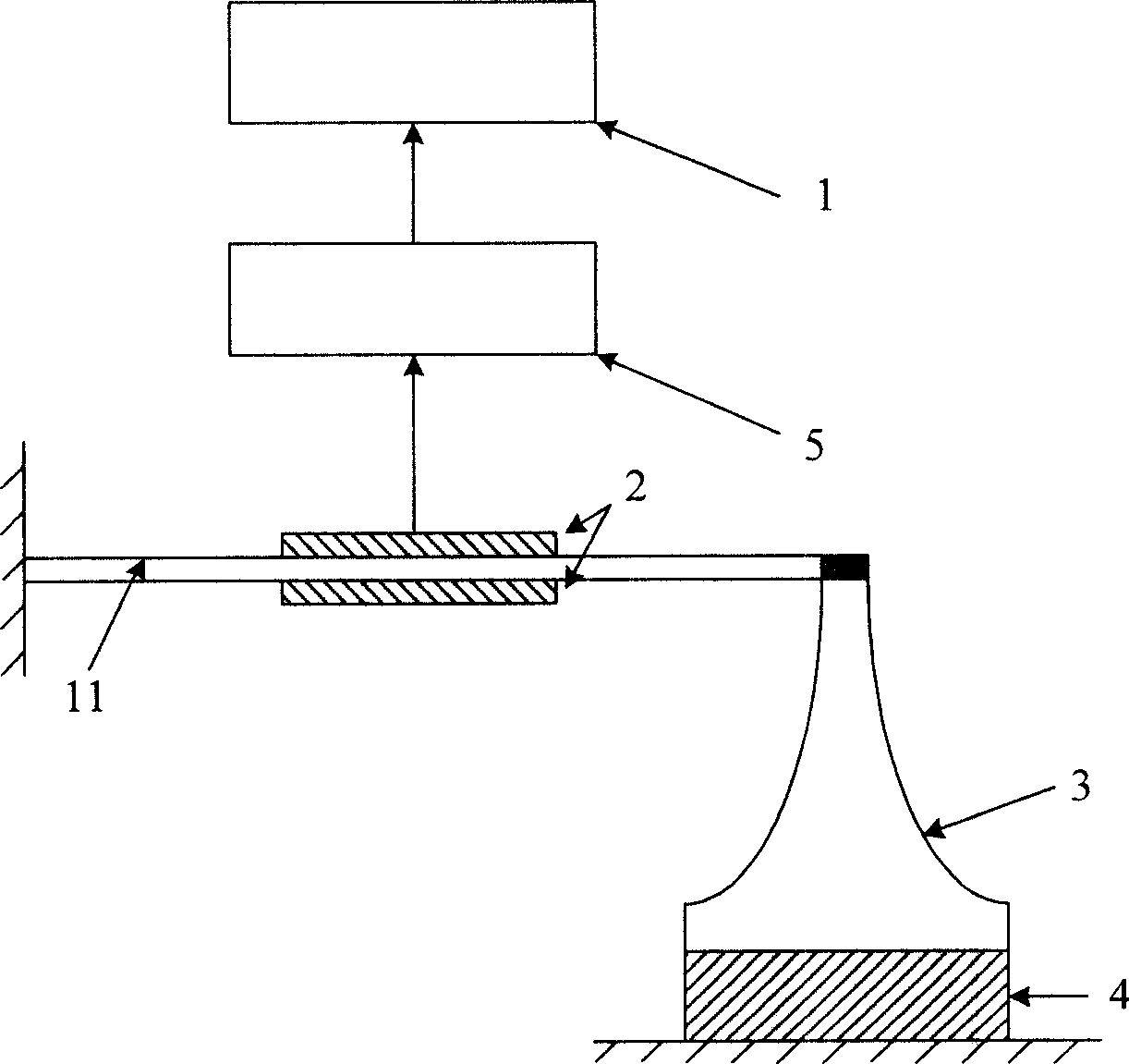
[0025] See figure 2 One end of the amplifying mechanism 3 in this example is connected to the magnetostrictive layer 4, and the other end is connected to the piezoelectric layer 2 through a cantilever beam 11, and the amplifying mechanism 3 is set at the end of the cantilever beam 11.
[0026] In the sensor described in this example, since the amplifying mechanism 3 of its self-powered mechanism transmits the strain amplification of the magnetostrictive material to the end point of the cantilever beam 11, the strain of the cantilever beam 11 is correspondingly amplified, thereby also making the piezoelectric layer 2 The output amplification improves the magnetoelectric conversion efficiency and the energy supply capacity of the system.
Embodiment 3
[0027] Embodiment 3: It is different from Embodiment 1 in that it uses a different self-powered mechanism, more specifically, the self-powered mechanism uses a different amplifying mechanism.
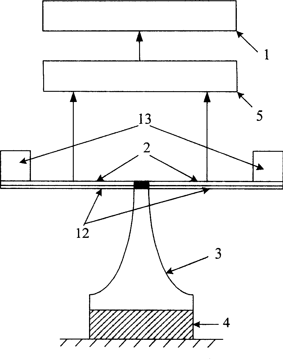
[0028] See image 3 One end of the amplifying mechanism 3 of this example is connected to the magnetostrictive layer 4, and the other end is connected to the piezoelectric layer 2 through a resonance beam 12, and the amplifying mechanism 3 is arranged at the midpoint of the resonance beam 12.
[0029] In order to obtain a better resonance effect, mass blocks 13 are added at both ends of the resonance beam 12 to further improve the sensitivity of the system.
PUM
 Abstract
Description
Claims
Application Information