Self-powered structure in use for sensor

A self-powered, sensor technology, applied in the direction of generators/motors, piezoelectric effect/electrostrictive or magnetostrictive motors, electrical components, etc., can solve the problem of reducing magnetoelectric conversion efficiency and energy output capacity, large loss, Low quality factor and other problems, to achieve the effect of increasing the resonant magnetoelectric conversion efficiency, improving the magnetoelectric voltage conversion coefficient, and improving the quality factor

Inactive Publication Date: 2009-09-23
CHONGQING UNIV
View PDF6 Cites 0 Cited by
  • Summary
  • Abstract
  • Description
  • Claims
  • Application Information

AI Technical Summary

Problems solved by technology

Due to the magneto-electromechanical interaction between the layers of the magnetoelectric material, the magnetoelectric conversion coefficient of the magnetoelectric material will be significantly improved near its resonance point, and studies have shown that it can generally be 1 to 2 orders of magnitude higher than the output of the non-resonant point (depending on the composite material quality factor), when the frequency of the exciting electromagnetic wave is equal to the natural frequency of the structure, a stronger resonance output will be obtained. However, the self-powered mechanism of this double-layer structure has a low quality factor, usually only tens to hundreds, Poor energy concentration and large loss seriously reduce its magnetoelectric conversion efficiency and energy output capability. In the usual weak magnetic field, it is difficult to supply power to circuits and sensors

Method used


Image

  • Self-powered structure in use for sensor
  • Self-powered structure in use for sensor
  • Self-powered structure in use for sensor

Examples


Embodiment 1

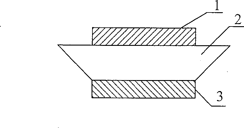
[0019] Embodiment 1: a kind of self-powered mechanism for sensor, it comprises magnetostrictive layer 1 and piezoelectric layer 3, it is characterized in that: between described magnetostrictive layer 1 and piezoelectric layer 3, amplifying mechanism is added 2.

[0020] The amplifying mechanism 2 is a mechanical quantity amplifying mechanism, such as a vibration amplifying mechanism, a force amplifying mechanism or a strain amplifying mechanism.

[0021] from figure 1 It can be seen from the figure that one end of the amplification mechanism 2 in this example is connected with the magnetostrictive layer 1 , and the other end is connected with the piezoelectric layer 3 .

[0022] In this example, due to the addition of an amplification mechanism, the mechanical stress or strain generated by the magnetostrictive material can be amplified, thereby making full use of the mechanical energy generated by the magnetostrictive layer and improving the magnetoelectric voltage conversio...

Embodiment 2

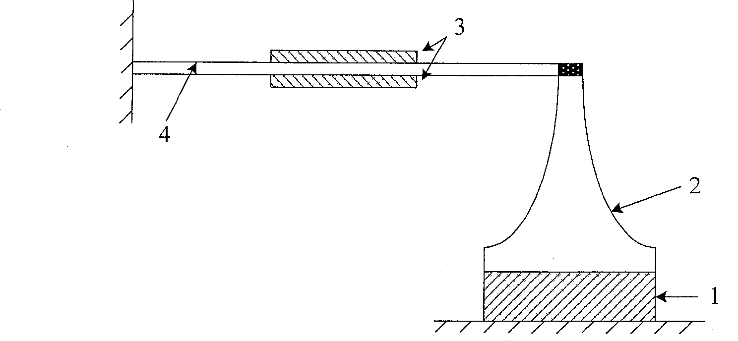
[0023] Embodiment 2: a kind of self-powered mechanism for sensor, it comprises magnetostrictive layer 1 and piezoelectric layer 3, it is characterized in that: between described magnetostrictive layer 1 and piezoelectric layer 3, amplifying mechanism is added 2. Amplifying mechanism 2 is a mechanism that can enhance the amplitude.

[0024] from figure 2 It can be seen from the figure that one end of the amplification mechanism 2 in this example is connected to the magnetostrictive layer 1 , and the other end is connected to the piezoelectric layer 3 through the cantilever beam 4 , and the amplification mechanism 2 is arranged at the end of the cantilever beam 4 .

[0025] In this example, the amplification mechanism 2 transmits the strain amplification of the magnetostrictive material to the end point of the cantilever beam 4, so that the strain of the cantilever beam 4 is correspondingly amplified, thereby also amplifying the output of the piezoelectric layer 3, and improvi...

Embodiment 3

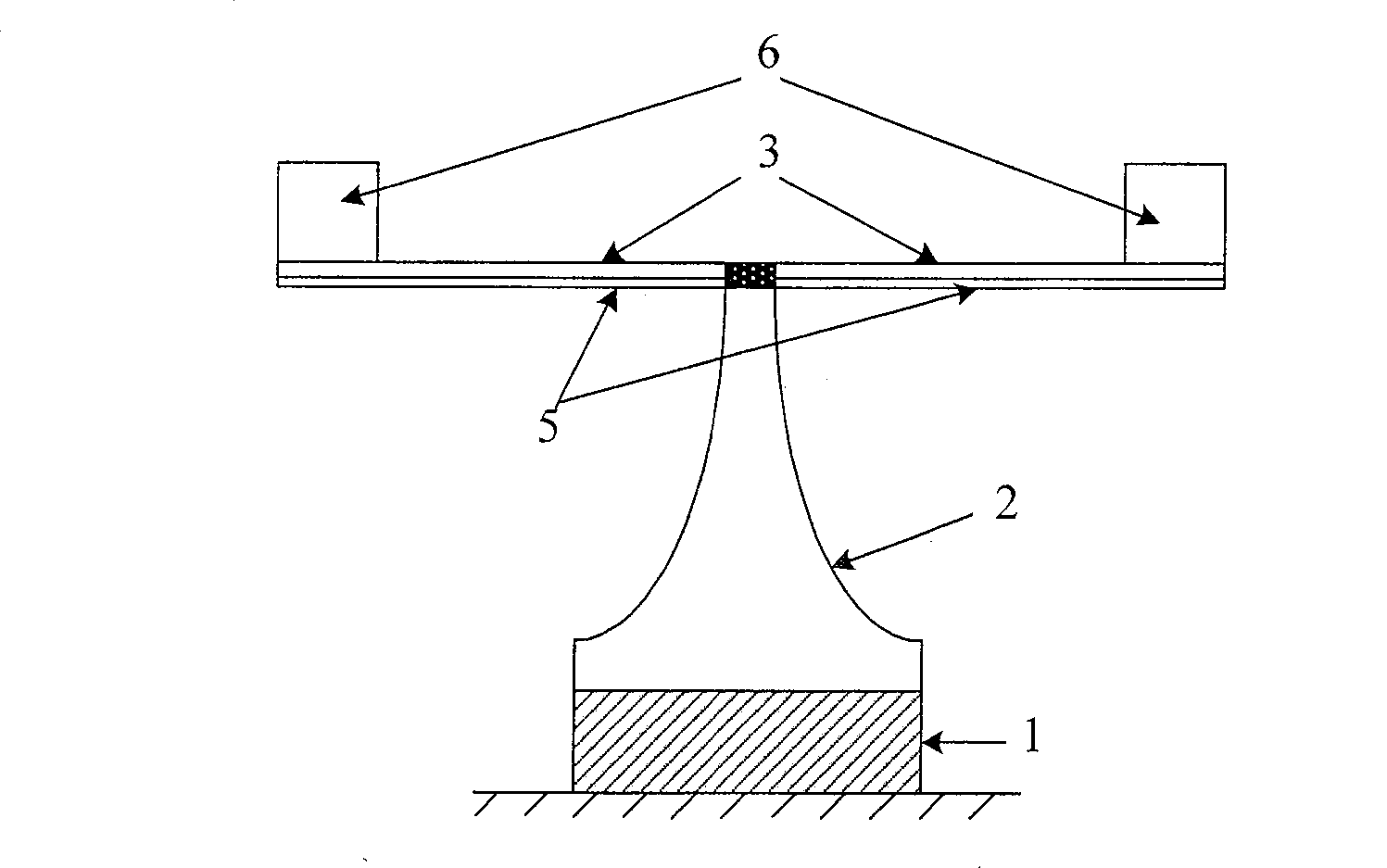
[0026] Embodiment 3: A self-powered mechanism for sensors, which includes a magnetostrictive layer 1 and a piezoelectric layer 3, characterized in that: an amplification mechanism is added between the magnetostrictive layer 1 and the piezoelectric layer 3 2.

[0027] The amplifying mechanism 2 is a mechanical quantity amplifying mechanism, such as a vibration amplifying mechanism, a force amplifying mechanism or a strain amplifying mechanism.

[0028] see image 3 One end of the amplifying mechanism 2 is connected to the magnetostrictive layer 1 , and the other end is connected to the piezoelectric layer 3 through the resonant beam 5 , and the amplifying mechanism 2 is arranged at the midpoint of the resonant beam 5 .

[0029] In this example, in order to obtain a better resonance effect, mass blocks 6 are added at both ends of the resonant beam 5, which further improves the sensitivity of the system.


PUM


Abstract

The invention relates to a self-powered mechanism for a sensor. It includes a magnetostrictive layer (1) and a piezoelectric layer (3), and is characterized in that an amplification mechanism (2) is added between the magnetostrictive layer (1) and the piezoelectric layer (3). Because the invention adds an amplification mechanism to the existing magnetoelectric composite mechanism, its quality factor is obviously improved, energy can be collected, and the magnetoelectric conversion efficiency is thus increased. This self-powered mechanism can also be used in micro-power circuits.

Description

technical field [0001] The invention relates to a power supply mechanism for sensors, in particular to a self-power supply mechanism for sensors. Background technique [0002] In a distributed passive, wireless multi-parameter array sensing system, the number of sensors distributed and the sensing distance are the most important factors affecting the application. Whether it is a sensing unit or a processing circuit, the supply of energy is the key to realizing an intelligent wireless sensor, that is, the realization of the so-called "self-powered". [0003] In the current passive wireless sensor, the energy is usually coupled to the interdigital transducer by the antenna, and then emitted by the same antenna after reflection. This type of sensor does not have any energy storage elements. Therefore, in the long-distance transmission When the distance and limited excitation energy, it is impossible to give enough signal energy to the receiving and processing circuits. Even i...

Claims


Application Information

Patent Timeline
Patent Type & Authority Patents(China)
IPC IPC(8): H02N2/00H02N2/02H02N2/18
Inventor 李平文玉梅卞雷祥郑敏杨帆
Owner CHONGQING UNIV
Why Eureka
Try Eureka