Optical sensor light switch

A sensor and switch technology, applied in the field of optical sensor lighting switches, can solve problems such as unsightly wall-mounted switches, increased switch costs, and failures.

Inactive Publication Date: 2007-02-21
AVAGO TECH ECBU IP (SINGAPORE) PTE LTD
View PDF0 Cites 12 Cited by
  • Summary
  • Abstract
  • Description
  • Claims
  • Application Information

AI Technical Summary

Problems solved by technology

Each switch of this type includes moving parts which often fail and add to the cost of the switch
Also, traditional wall switches are often unsightly, but are put up with because of the functionality they provide

Method used


Image

  • Optical sensor light switch
  • Optical sensor light switch
  • Optical sensor light switch

Examples


Embodiment Construction

[0013] In the following detailed description, reference is made to the accompanying drawings, which form a part hereof, and which show specific embodiments of the invention as may be practiced. To this end, directional terms such as "top", "bottom", "front", "rear", etc. are used with reference to the orientation of the figures being described. Because components of embodiments of the present invention may be oriented in many different orientations, directional terminology is for purposes of illustration only and not limitation. It is to be understood that other embodiments may be utilized and structural or logical changes may be made without departing from the scope of the present invention. Accordingly, the following detailed description should not be taken as limiting, but the scope of the invention is defined by the claims.

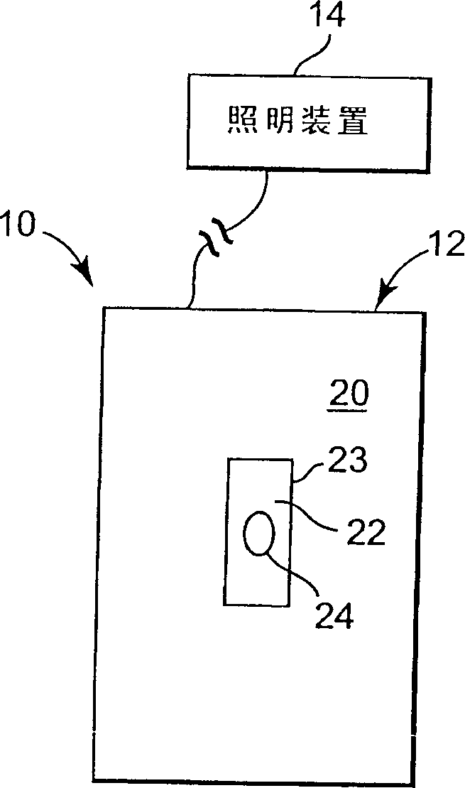
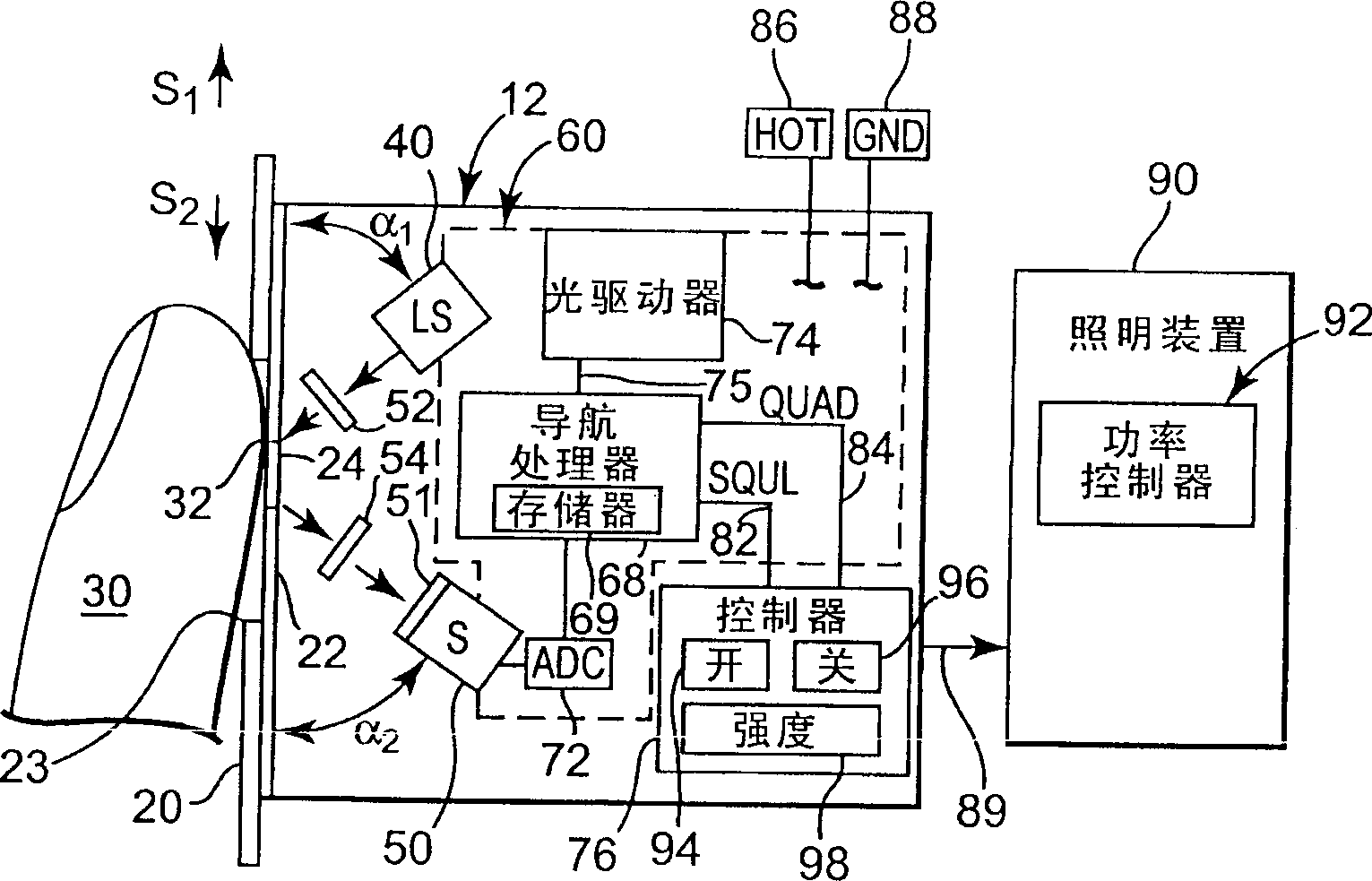
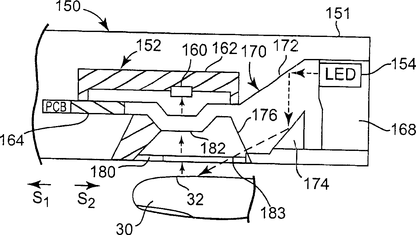
[0014] Embodiments of the present invention focus on controlling a lighting device with an optical switch that has no moving parts and is capable of...


PUM


Abstract

A switch for controlling a lighting device includes a contact surface, a light source, and an optical navigation sensor. The contact surface includes a generally transparent zone and is configured for removably receiving a fingertip adjacent to the transparent zone. The light source is configured to illuminate the transparent zone of the contact surface. The optical navigation sensor is configured to sense relative motion of the illuminated fingertip at the transparent zone to modify a function of a lighting device external to the light switch based on the relative motion.

Description

technical field [0001] The invention relates to an optical sensor lighting switch. Background technique [0002] Almost everyone has had the dilemma of being in a room that is too brightly lit for the room they want to use. However, the absence of lighting in a room renders the room unusable. One traditional way to deal with this situation is to install a dimmer switch, which can change the lighting intensity of the room to the desired intensity. Traditional dimmer switches typically include some form of circuitry to adjust the voltage supplied to the lamp. In one example, a circuit known as a triac (eg, a silicon controlled rectifier) ​​is used to vary the voltage by controlling the waveform of the alternating current. Triac circuits are commonly referred to as TRIACs. [0003] There are many difficulties with effectively operating a dimmer switch, including radio frequency interference, power harmonics, heat, and the non-linear current demand of an incandescent light b...

Claims


Application Information

Patent Timeline
IPC IPC(8): H05B37/02H01H9/00
CPCH03K17/9631H05B37/0209H05B47/165H05B47/17H01H35/00H03K17/78
Inventor 约翰·S·温斯特兰德
Owner AVAGO TECH ECBU IP (SINGAPORE) PTE LTD
Why Eureka
Try Eureka