

Pest repelling device
A technology for pests and chemical chambers, which is applied in the field of pest repelling devices, can solve the problems of increasing the height of the device, and achieve the effects of reducing height, long contact length and good divergence effect.
- Summary
- Abstract
- Description
- Claims
- Application Information
AI Technical Summary
Problems solved by technology
Method used
Image

Examples
Embodiment Construction
[0024] The specific embodiments of the present invention will be described below in conjunction with the accompanying drawings.
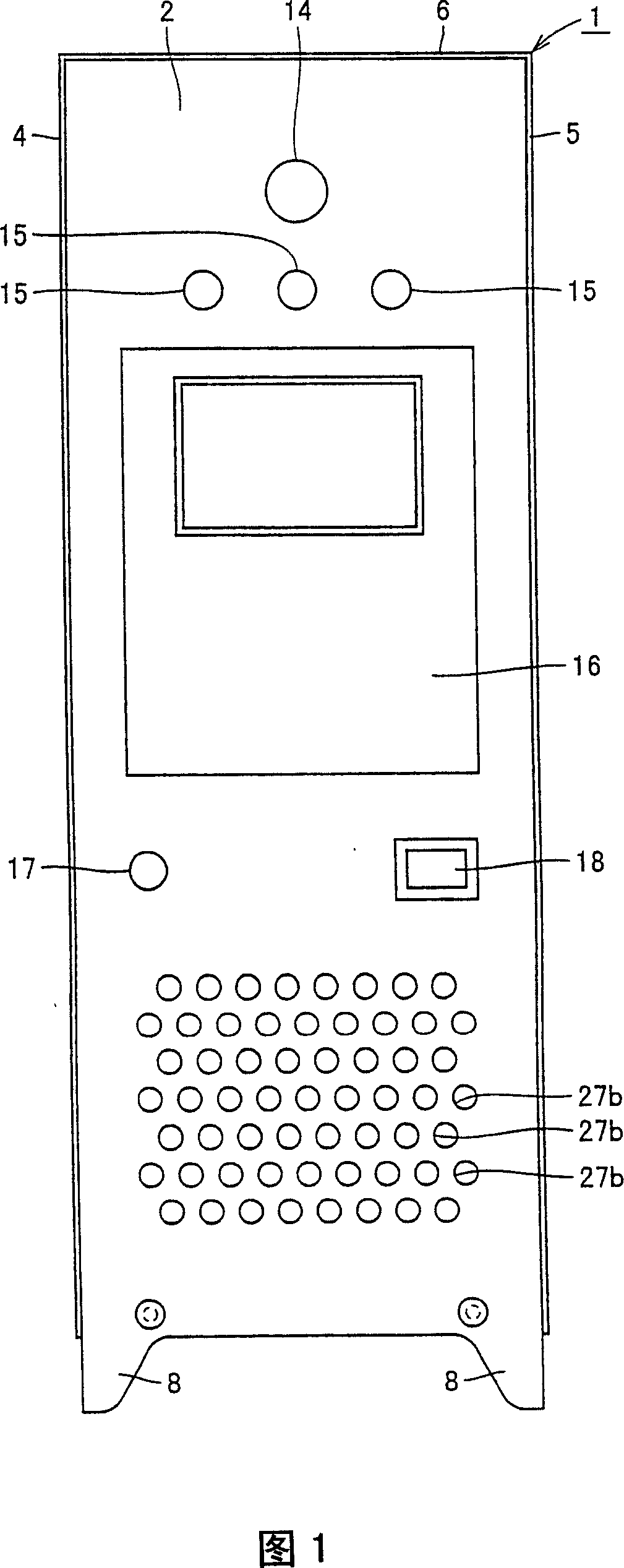
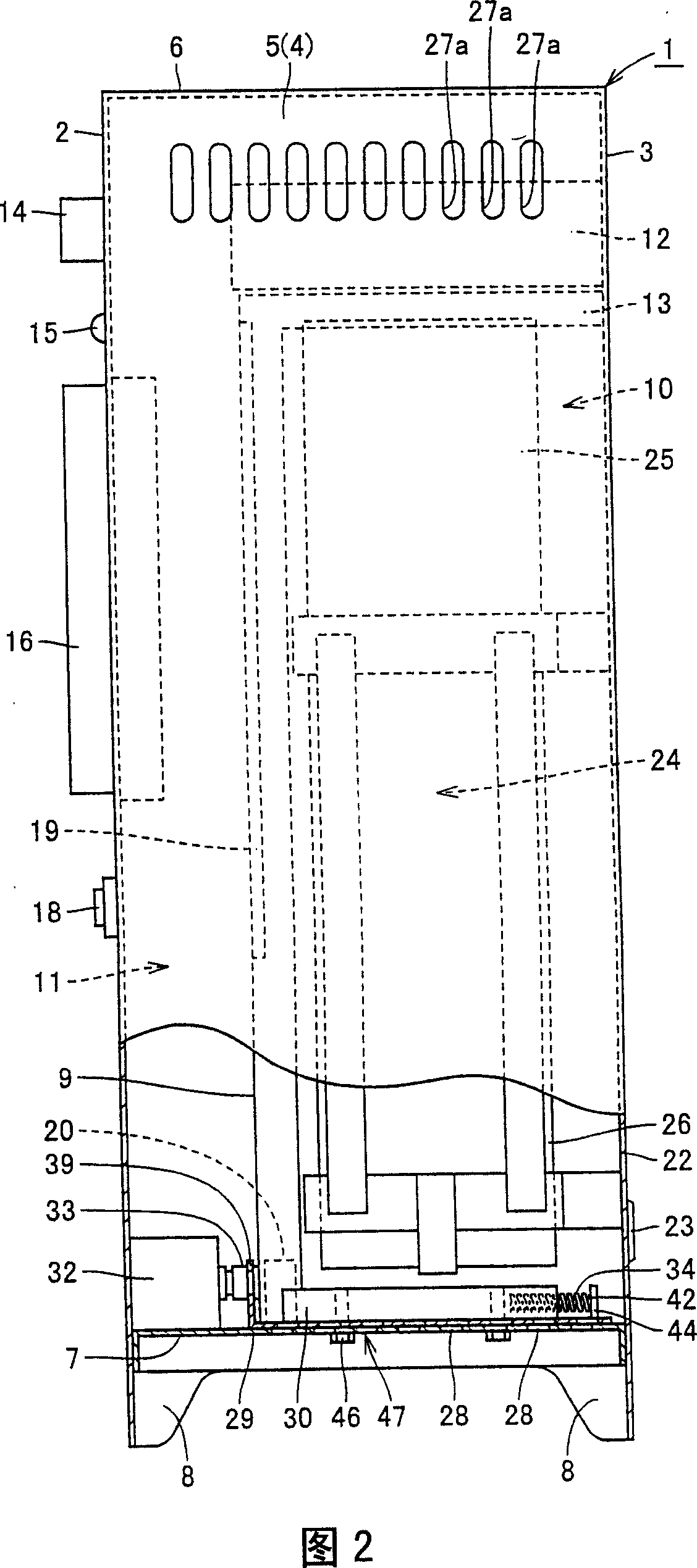
[0025] In Figs. 1 and 2, the pest expelling device of the present invention is installed in kitchens of restaurants, hotels, etc., to drive away pests such as cockroaches. The pest expelling device has a casing 1 . The housing 1 is a cube (cuboid) having a front 2 , a rear 3 , a left side 4 , a right side 5 , an upper side 6 and a bottom side 7 . Legs 8 extending downward from the bottom surface 7 are provided on the box body 1 . The foot portion 8 is formed at the lower portions of the front face 2 and the rear face 3 .
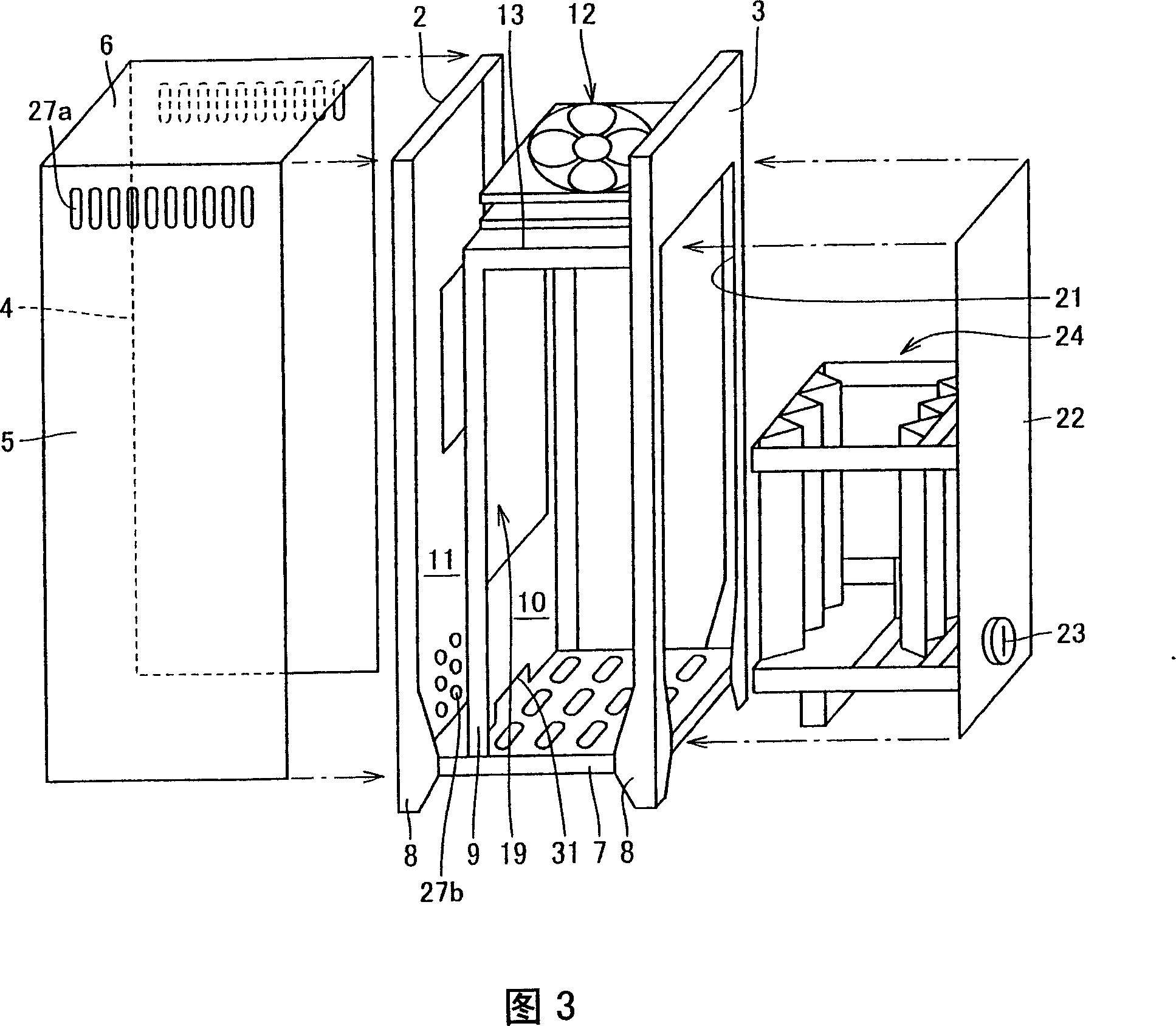
[0026] The inside of the box body 1 is divided into a drug chamber 10 and an electrical appliance chamber 11 by a partition 9 provided between the front face 2 and the rear face 3 .
[0027] The upper part of the medicine chamber 10 is separated from the electrical equipment chamber 11 by a fan 12 .
[0028] The above-mentione...
PUM
 Abstract
Description
Claims
Application Information