Six-coordinate linkage fibre wrapping machine

A technology of fiber winding machine and coordinates, applied in the field of fiber winding machines

Inactive Publication Date: 2007-02-28
HARBIN INST OF TECH
View PDF0 Cites 12 Cited by
  • Summary
  • Abstract
  • Description
  • Claims
  • Application Information

AI Technical Summary

Problems solved by technology

[0003] In order to solve the problem that the existing technology cannot satisfy the winding forming of complicated special-shaped components, the present invention provides a six-coordinate linkage fiber winding machine, which includes a mandrel C-axis rotary motion assembly 1 and a Z-coordinate linear motion assembly 2 , Y-coordinate linear motion assembly 3 and X-coordinate linear motion assembly 4, the center line of the return transmission axis of the mandrel C-axis rotary motion assembly 1 is parallel to the motion direction of the Z-coordinate linear motion assembly 2; the Z-coordinate linear motion assembly The trolley 21 in 2 is set above the base 22 of the Z-coordinate linear motion, the support 31 of the Y-coordinate linear motion assembly 3 is fixed above the trolley 21, and the X-coordinate linear motion assembly 4 is set on the Y-coordinate linear motion assembly 3 On one side, it also includes the B-axis rotary motion assembly 5 and the A-axis rotary motion assembly 6, the B-axis rotary motion assembly 5 is fixedly arranged on the shell 42 of the X-coordinate linear motion assembly 4 near the mandrel C-axis At one end of the rotary motion assembly 1, the B-axis rotary motion assembly 5 includes a first servo motor 51, a first reduction gear 52, a first box body 53, a first transmission shaft 54 ​​and a connecting flange 55, and the first reduction gear 52 is placed In the first box body 53, the first servo motor 51 is fixedly connected to the first box body 53 and the output gear of the first servo motor 51 meshes with the first reduction gear 52, and the first transmission shaft 54 ​​and the first reduction gear 52 is coaxially fixedly connected and the upper end of the first transmission shaft 54 ​​passes through the upper cover of the first box body 53 and is fixedly connected with the connecting flange 55. The axis line of the first transmission shaft 54 ​​is parallel to the Y coordinate; the A axis rotates The motion assembly 6 includes a second servo motor 61, a second reduction gear 62, a second casing 63, a second transmission shaft 64 and a yarn output swing head 65, and the bottom surface of the second casing 63 of the A-axis rotary motion assembly 6 It is fixedly connected with the connecting flange 55 of the B-axis rotary motion assembly 5, the second reduction gear 62 is placed in the second box body 63, the second servo motor 61 is fixedly connected with the second box body 63 and the second servo motor The output gear of 61 meshes with the second reduction gear 62, the second transmission shaft 64 is coaxially fixedly connected with the second reduction gear 62 and the axis line of the second transmission shaft 64 is parallel to the X coordinate, and the axis line of the second transmission shaft 64 is parallel to the core The opposite end of the mold C-axis rotary motion assembly 1 passes through the second box body 63, and the end is fixedly provided with a yarn output swing head 65

Method used


Image

  • Six-coordinate linkage fibre wrapping machine
  • Six-coordinate linkage fibre wrapping machine
  • Six-coordinate linkage fibre wrapping machine

Examples


specific Embodiment approach 1

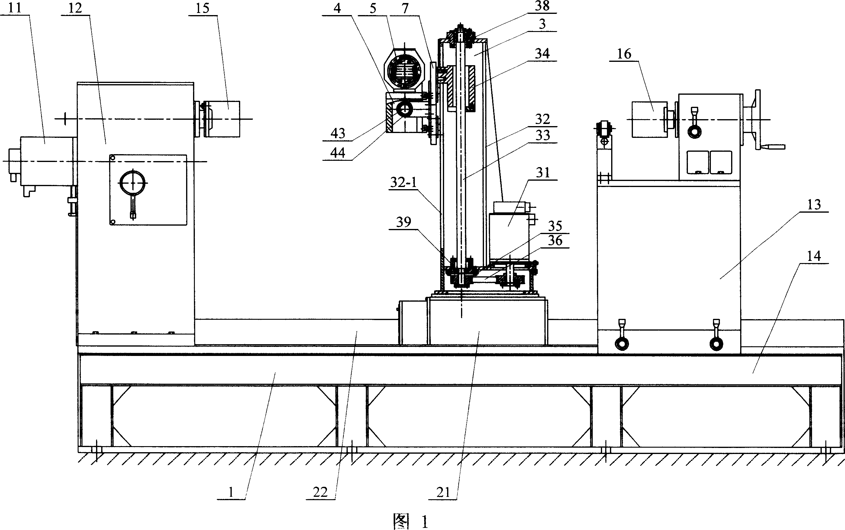
[0006] Specific implementation mode 1: (see Fig. 1-Fig. 6) This embodiment consists of mandrel C-axis rotary motion assembly 1, Z-coordinate linear motion assembly 2, Y-coordinate linear motion assembly 3, and X-coordinate linear motion assembly 4 , B-axis rotary motion assembly 5 and A-axis rotary motion assembly 6, the core mold C-axis rotary motion assembly 1's return transmission axis center line is parallel to the Z coordinate linear motion assembly 2's motion direction; Z coordinate linear motion The trolley 21 of the assembly 2 is set above the Z-coordinate linear motion base 22, the bracket 31 of the Y-coordinate linear motion assembly 3 is fixedly set above the trolley 21, and the X-coordinate linear motion assembly 4 is set on the Y-coordinate linear motion assembly On one side of 3, the B-axis rotary motion assembly 5 is fixedly arranged on one end of the C-axis rotary motion assembly 1 near the mandrel on the shell 42 of the X-coordinate linear motion assembly 4, an...

specific Embodiment approach 2

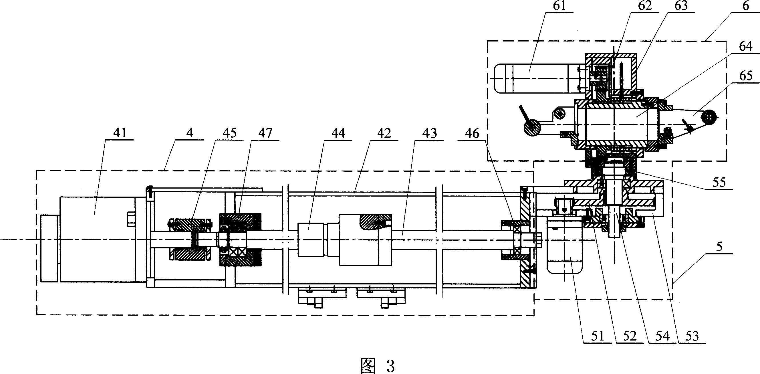
[0007] Specific embodiment two: (see Fig. 1-Fig. 5) the difference between this embodiment and specific embodiment one is that it also includes connecting plate 7, and described X-coordinate linear motion assembly 4 includes the 3rd servomotor 41, shell 42 , the first lead screw 43, the first lead screw nut 44, the coupling 45, the first lead screw support 46 and the second lead screw support 47, one end of the C-axis rotary motion assembly near the core mold in the inner cavity of the housing 42 is provided There is a first leading screw support 46 and the other end of the casing 42 is fixedly provided with a third servo motor 41, and the middle part of the casing 42 cavity is provided with a second leading screw support 47; one end of the first leading screw 43 is connected to the first Leading screw support 46 is rotationally connected, and the other end of described first leading screw 43 passes second leading screw support 47 and is fixedly connected with the output shaft ...

specific Embodiment approach 3

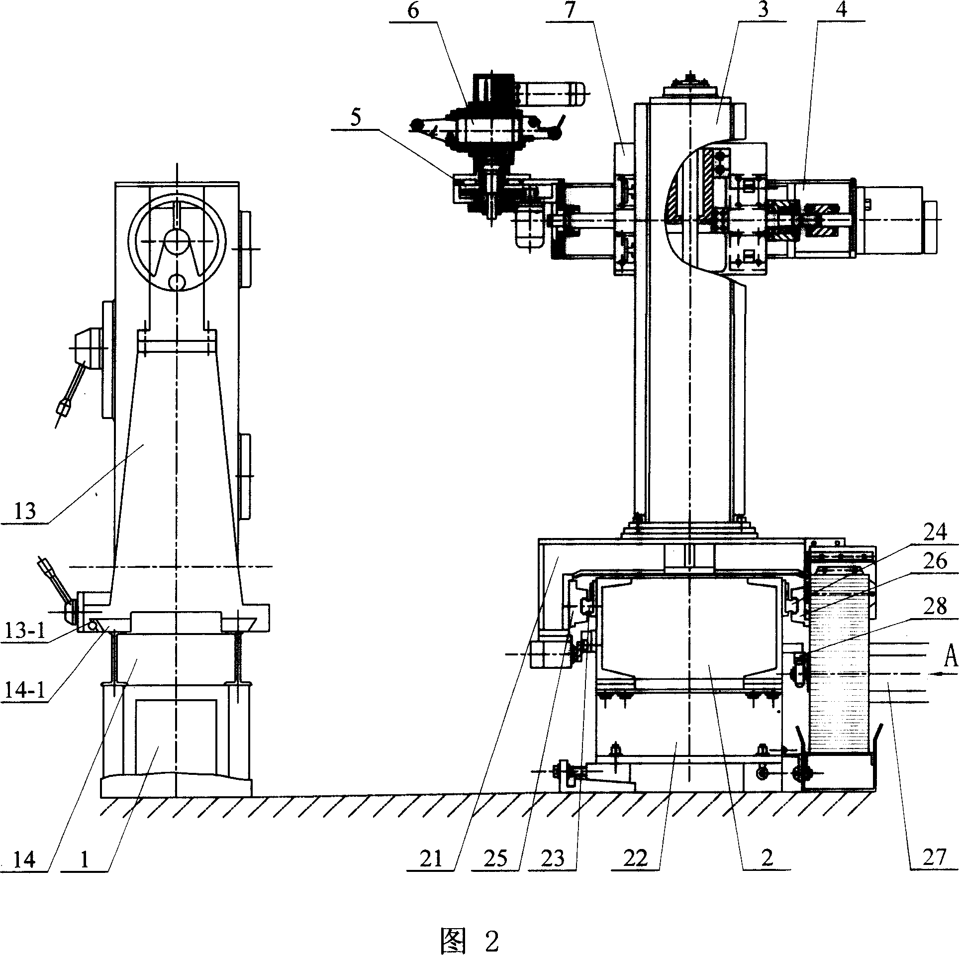
[0008] Specific embodiment three: (see Fig. 1, Fig. 2, Fig. 6) the difference between this embodiment and specific embodiment one or two is that the Z-coordinate linear motion assembly 2 also includes a fifth servo motor 27 and a rack 28 The upper part of the two side walls of the Z-coordinate linear motion base 22 is respectively provided with a No. 1 guide rail 23 and a No. 2 guide rail 24, and a No. 1 guide groove matching with the No. 25 and No. 2 guide groove 26; rack 28 is fixedly arranged on the outer surface of Z coordinate linear motion base 22 one side, the output gear of the 5th servo motor 27 meshes with rack 28 and servo motor 27 is fixed on the dolly 21. Other compositions and connections are the same as those in Embodiment 1 or Embodiment 2.


PUM


Abstract

The invention discloses a six-coordinate linked fiber coiler, which is characterized by the following: the movement of six-coordinate is realized by controlling six servo motors, the back driving axial line of core mould C shaft parallels the moving direction of Z-coordinate straight-line movement unit assemblage (2), the X-coordinate straight-line movement unit assemblage (4) is set on one side of Y-coordinate straight-line movement unit assemblage (3), the B-axle rotary moving unit assemblage (5) is fixed on one end of near-core mould C rotary moving unit assemblage on the case (42) of X-coordinate straight-line moving unit assemblage, the bottom of second box (63) of A-axle rotary moving unit assemblage (6) connects the connecting flannel (55) of B-axle rotary moving unit assemblage (5), the spinning swaying head (65) is fixed on the opposite end of core mould C-axle rotary moving unit assemblage on the second driving shaft (64).

Description

technical field [0001] The invention relates to a fiber winding machine. Background technique [0002] With the development of composite material processing technology, fiber winding has developed rapidly as a relatively new processing technology. The development of fiber winding machine has become a necessary way to improve the manufacturing quality of composite material products. Its control system is controlled by mechanical system, hydraulic pressure The servo system is developed to the microcomputer control system, which gradually adapts to the production needs. Multi-shaft multi-motion shaft winding machine has become the mainstream direction of research and development. At present, there have been two-axis to four-axis CNC linkage fiber winding machines on the market, but these are still far from being able to meet the winding forming of some complex components, such as tee pipes, blades and other non-rotating special-shaped components. . Contents of the invention...

Claims


Application Information

Patent Timeline
Patent Type & Authority Applications(China)
IPC IPC(8): B29C70/28B29C70/54B29C70/40
Inventor 路华王永章韩德东富宏亚付云忠韩振宇
Owner HARBIN INST OF TECH
Why Eureka
Try Eureka