Zinc electrolysis direct current coating technology for new anode plate

A technology of anode plate and zinc electrolysis, applied in the direction of electrodes, photographic technology, electrolysis process, etc., can solve the problems of limited production quantity and affecting product quality, achieve the effect of improving production efficiency and ensuring supplementary supply

Inactive Publication Date: 2010-05-12
HENAN YUGUANG GOLD & LEAD
View PDF3 Cites 0 Cited by
  • Summary
  • Abstract
  • Description
  • Claims
  • Application Information

AI Technical Summary

Problems solved by technology

Although this method is simple to operate, the production quantity is limited, and the industrial application has certain limitations, especially when the production fluctuates and large quantities of new anode plates are required.
In addition, when a large number of new anode plates are put into the electrolytic cell for natural passivation, it is easy to affect the product quality

Method used


Image

  • Zinc electrolysis direct current coating technology for new anode plate
  • Zinc electrolysis direct current coating technology for new anode plate

Examples


Embodiment Construction

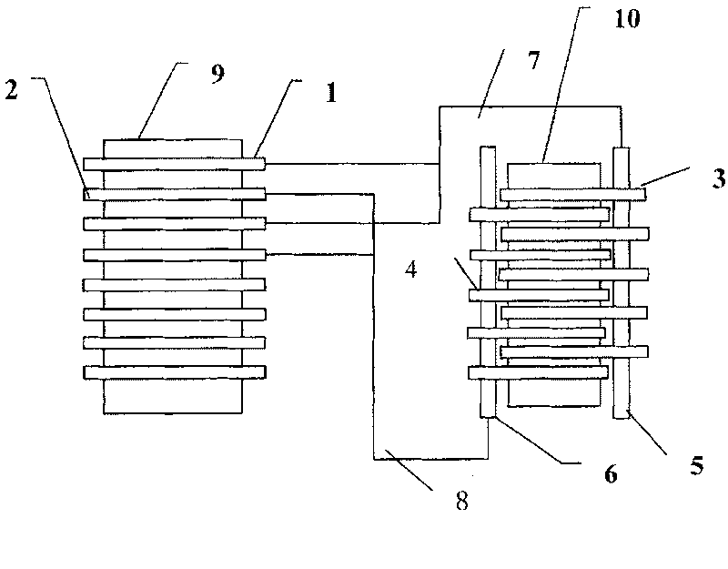
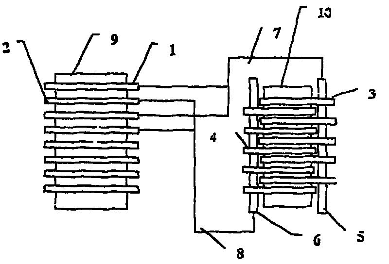
[0010] Such as figure 1 As shown, a new anode plate DC electroplating process for zinc electrolysis is specifically as follows: the flat cathode plate 3 and the anode plate 4 to be coated are installed in the coating tank 10, and the cathode plate 3 and the anode plate 4 are evenly distributed in a staggered manner. Conductor 7 (positive pole conductor) leads down positive pole from the anode plate 1 on the electrolytic cell 9 and is connected on the anode bus bar 5 on the coating tank 10, and the anode plate and the anode bus bar adopt an overlapping connection mode, and the conductor 8 ( Negative pole conductor) leads down from the cathode plate 2 on the electrolytic cell 9 and is connected to the cathode plate busbar 6 on the coating tank 10, and the cathode plate and the cathode busbar also adopt an overlapping connection mode to form a whole circuit. The anode plate in the coating tank 10 is used for coating production.

[0011] The distance between the cathode plate 3 a...


PUM


Abstract

The invention relates the coating film technology, comprising the following steps: installing the negative plate and anode plate in the coating groove, alternative distributing negative plate and anode plate, the positive pole of anode plate on electrolysis bath is connected with the anode bus wire on coating groove by conductor, the anode plate being connected with anode bus wire by overlapping,the negative pole of negative plate on electrolysis bath is connected with the negative bus wire on coating groove by conductor, and the negative plate being connected with negative bus wire by overlapping. The technology improves the production efficiency.

Description

Technical field: [0001] The invention belongs to the technical field of hydrosmelting zinc electrolysis production, and in particular relates to a direct-current electroplating process for new anode plates of zinc electrolysis. Background technique: [0002] At present, the new anode plate coating in the same industry in China adopts the coating method of placing the flattened anode plate at the end of the electrolytic tank and performing natural passivation under the action of the electric field of the electrolytic tank. Although this method is simple to operate, the production quantity is limited, and the industrial application has certain limitations, especially when the production fluctuates and large batches require new anode plates to be put in. In addition, when a large number of new anode plates are put into the electrolytic cell for natural passivation, it is easy to affect the product quality. Invention content: [0003] In order to overcome the above-mentioned ...

Claims


Application Information

Patent Timeline
Patent Type & Authority Patents(China)
IPC IPC(8): C25C7/02C25C1/16
CPCY02P10/20
Inventor 白四清程利军邓宏伟段永康
Owner HENAN YUGUANG GOLD & LEAD
Why Eureka
Try Eureka