Rotational flow pulverized coal burner

A technology for burners and swirl generators, which is applied in the direction of burners, burners for burning powder fuel, combustion methods, etc., which can solve the problems of high energy consumption, reduced effect of thick-thin separation, large resistance, etc., and achieve nitrogen oxide emissions The effect of low consumption, good combustion stability and high swirl intensity

Active Publication Date: 2007-02-28
DONGFANG BOILER GROUP OF DONGFANG ELECTRIC CORP
View PDF1 Cites 32 Cited by
  • Summary
  • Abstract
  • Description
  • Claims
  • Application Information

AI Technical Summary

Problems solved by technology

However, due to the use of the Venturi tube and the spindle body or the finned spindle body as the main injection (air and powder mixing) device, although the separation of the concentration of pulverized coal can be achieved, the resistance is large and the effect is poor. High requirements and high energy consumption; in addition, a flame stabilizer composed of a ring and a cone is set at the end of the secondary air nozzle, a part of the ring protrudes into the outlet of the secondary nozzle, and the ring of the ring The end face of the inner circumference is a plurality of rectangular teeth arranged in a ring, and all the rectangular teeth (protrusions) protrude toward the center of the air powder (main) nozzle. The function of the flame stabilizer is to act as an obstacle to hinder the primary airflow (main nozzle) and Secondary airflow (nozzle) to reduce the air pressure downstream of it and help to ignite pulverize

Method used


Image

  • Rotational flow pulverized coal burner

Examples


Embodiment Construction

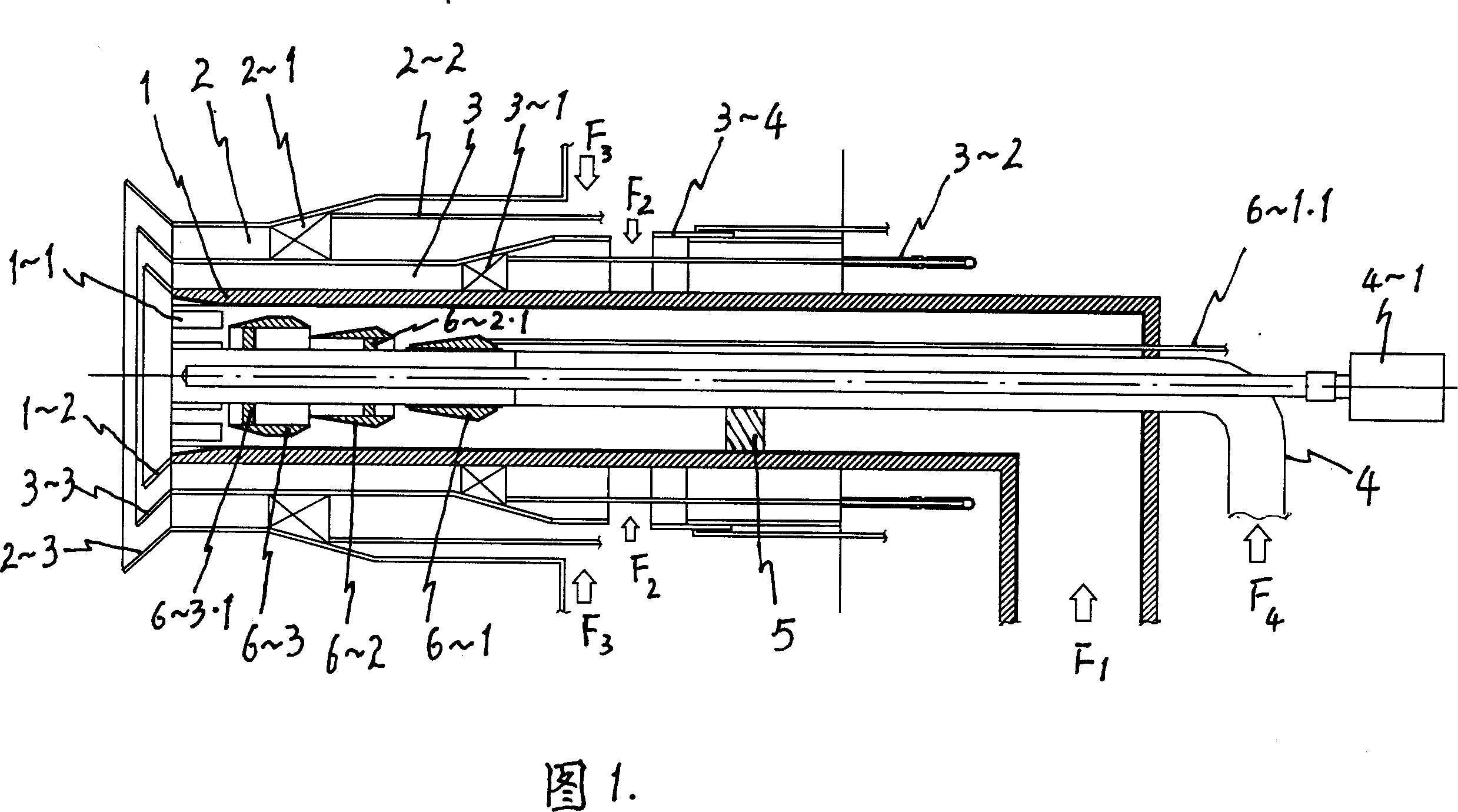
[0009] The total length of the burner is 7190mm, of which: the main body of the central cylinder 4 is 5160mm long, and 3 fixed plates 5 are arranged in the main nozzle 1 to fix the nozzle, the length of 4-1 oil gun is 6990mm, and the diameter of the pipe body is φ38mm. The main nozzle 1 is 4500mm long, the inner diameter of the nozzle cavity is φ590mm, and the wall thickness of the pipe body is 60mm. 30°, set 16 at equal arc intervals. The first-level thick-thin separation mechanism 6~1 has an axial length of 347mm, the maximum outer diameter φ315mm, and is slidably matched with the central cylinder 4 and adjusted axially by adjusting the pull rod 6~1.1. The second and final thick-thin separation mechanisms 6~2, 6~3 This embodiment is all fixed, through its supporting plates 6-2.1 and 6-3.1 and the central cylinder 4 are welded into one body, wherein the two-stage thick-lean separation mechanism 6-2 has an axial length of 335mm, and the inner and outer diameters are respective...


PUM


Abstract

The invention relates to a cyclone power coal burner used in the boiler of power station, wherein it comprises: oil gun, or central cylinder, 2-3 step power coal separator, the main nozzles of wedge groove and horn open; 2-3 air nozzles with cyclone generator and horn open, nozzles and gas inlet of central cylinder; at the surface of inner chamber of main nozzle, the inner and outer surfaces of separator, and at the surface of support plate, there are abrasion-resistant layer. The invention has better dense-thin separation effect, while the ratio between dense and thin is 3-7:1; the cyclone strength at 2-3 step nozzle is high with simple adjustment; the resistance of main nozzle is 1/3 of background technique to reduce 55-65% of energy consumption, with low nitrogen oxide discharge and stable burning.

Description

technical field [0001] The invention belongs to a spray type swirl burner used in conjunction with a pulverized coal-fired power plant boiler. The coal powder concentration distribution at the main nozzle of the burner is thick on the outside and light on the inside, and can realize ideal thick-lean combustion when matched with the corresponding boiler. Background technique [0002] Swirling pulverized coal burners are widely used in power plant boilers that use pulverized coal to achieve thick and thin combustion. At present, it is mainly a jet-type double air-regulating swirl burner, such as the "powdered coal burner" disclosed in the patent document with the publication number CN1271826A and the title "Powdered Coal Burner and Combustion Device Using the Pulverized Coal Burner". It belongs to this type of swirl pulverized coal burner. The burner includes a pulverized coal (wind-powder mixing) nozzle which is composed of a Venturi tube and a spindle as a pulverized coal c...

Claims


Application Information

Patent Timeline
IPC IPC(8): F23D1/02
Inventor 刘泰生张山鹰叶恩清但家瑜姚本荣霍锁善谢佳李燎李季梅文斌
Owner DONGFANG BOILER GROUP OF DONGFANG ELECTRIC CORP
Why Eureka
Try Eureka