
Adjustable pedal assembly

A technology of components and pedals, applied in the direction of control/adjustment system, layout of power plant control mechanism, control components, etc., can solve the problem of large-scale overall system, achieve simple composition method, reduce production cost, and reduce the number of parts Effect

Inactive Publication Date: 2007-02-28
KOREA AUTOMOTIVE TECH INST
View PDF1 Cites 8 Cited by
  • Summary
  • Abstract
  • Description
  • Claims
  • Application Information

AI Technical Summary

Problems solved by technology

However, this structure has a problem of increasing the overall size of the system due to the need to install brackets

Method used


Image

  • Adjustable pedal assembly
  • Adjustable pedal assembly
  • Adjustable pedal assembly

Examples


Embodiment Construction

[0033] The preferred implementation of the position-adjustable pedal assembly of the present invention will be described in detail below with reference to the accompanying drawings.

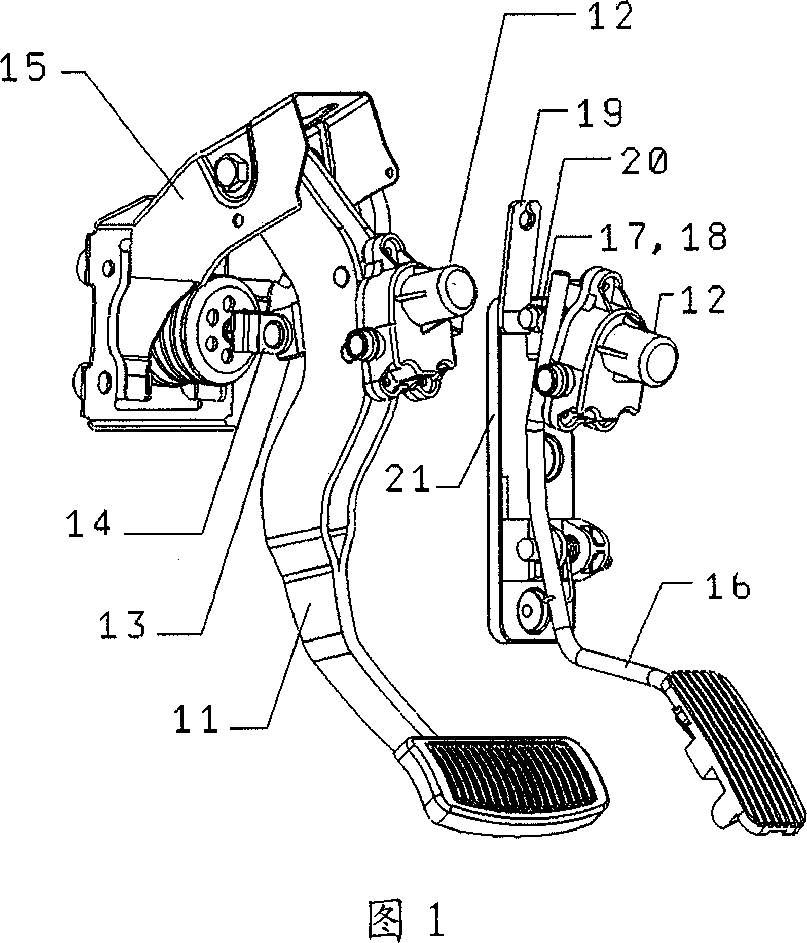
[0034] Fig. 1 is a perspective view showing a pedal assembly of the present invention, the left side view shows a case of being used in a brake pedal assembly, and the right side view shows a case of being used in an accelerator pedal.

[0035] First, the brake pedal assembly will be described. The brake pedal assembly related to the present invention has: a brake pedal arm 11b, which is pivotally supported and fixed on a brake pedal bracket 15, and the brake pedal bracket 15 is installed on the vehicle frame; It is provided at the end of the brake pedal arm 11b; and the speed reducer 12 is fixed on the brake pedal arm 11b.

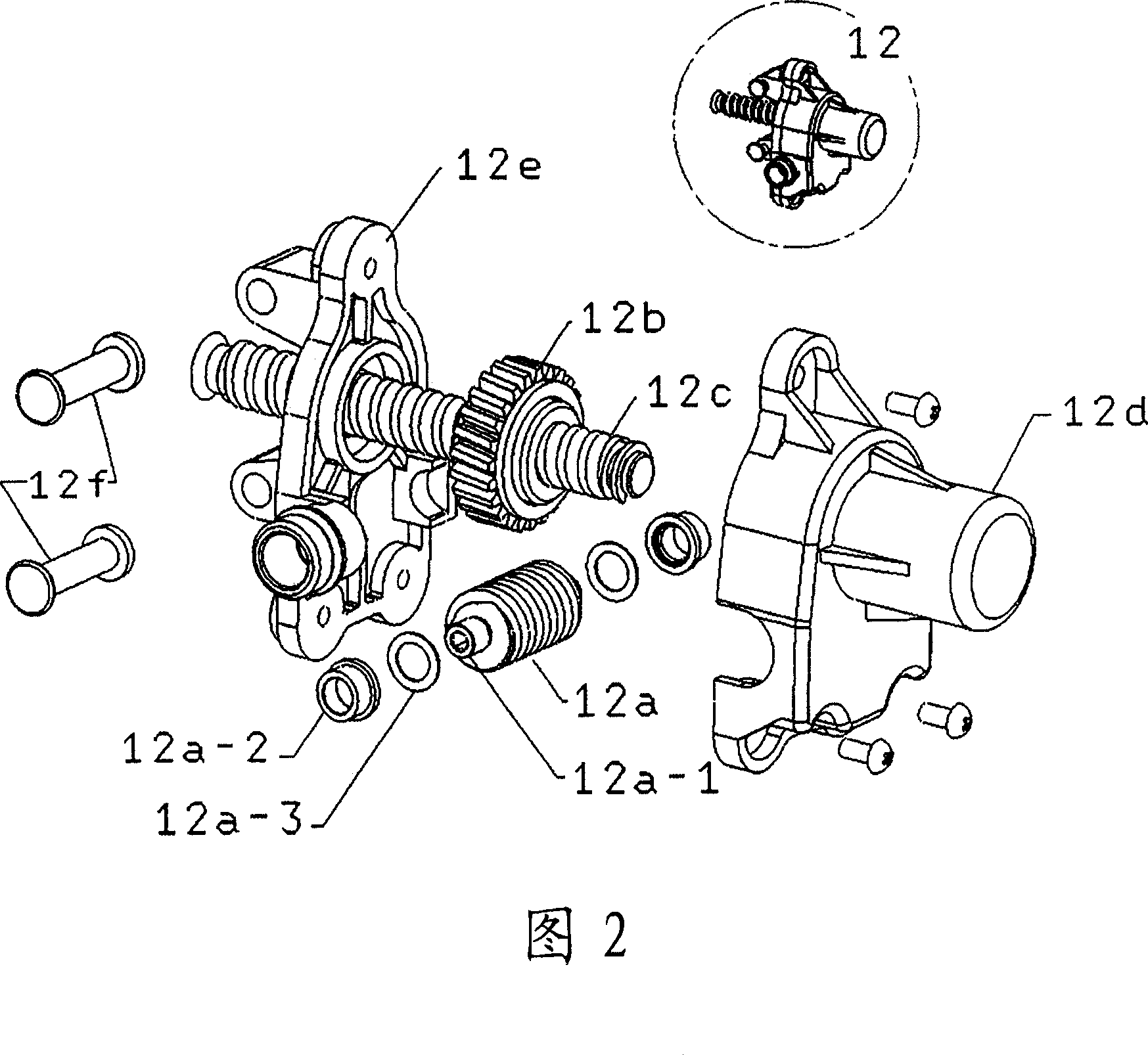
[0036] FIG. 2 is an exploded perspective view showing the speed reducer 12 . The speed reducer 12 has: a worm wheel 12a that transmits a driving force from a predetermined...


PUM


Abstract

The present invention provided a pedal assembly capable of position adjustment in a brake pedal assembly and an acceleration pedal assembly to be used for drive operation of a vehicle. The adjustable pedal assembly includes a pedal arm hingeably mounted to a support bracket, a pedal part disposed at an end portion of the pedal arm, a gear assembly fixedly mounted to the pedal arm, and driving means for driving the gear assembly. The gear assembly includes a first gear part for receiving a driving force of the driving means, and a second gear part engaged with the first gear part for moving the gear assembly according to a driving direction of the first gear part to thereby change a position of the pedal arm.

Description

technical field [0001] The invention relates to a position-adjustable pedal assembly, in particular to a position-adjustable pedal assembly for a brake pedal assembly and an accelerator pedal assembly used for vehicle driving operation. Background technique [0002] At the end of the pedal assembly of the vehicle, a pedal operated by the operator is installed. Due to the different physical conditions of the operator, it is often necessary to adjust the relative position of the pedal to the operator. Such relative position adjustment is generally performed by moving the operator's seat in the vehicle front-rear direction. That is, when the distance between the pedal and the operator is far, the seat is moved to the front of the vehicle, and when the distance between the pedal and the operator is short, the seat is moved to the rear of the vehicle to adjust its relative position. [0003] However, when the distance between the operator and the steering wheel of the vehicle is...

Claims


Application Information

Patent Timeline
Patent Type & Authority Applications(China)
IPC IPC(8): G05G1/14B60K26/02B60T7/04B60T7/06G05G1/40
CPCY10T74/20528G05G1/405B60T7/06
Inventor 宋世日朴正源李东原
Owner KOREA AUTOMOTIVE TECH INST
Learn More