

Terminal tray and lighting device with the same
A terminal plate and terminal technology, which is applied to the parts, electrical components, bases/shells of connecting devices, etc., can solve the problems of difficulty in high dimensional accuracy, easy to generate distortion or pores, and difficulty in mass production, and achieve excellent fire resistance. Effect
- Summary
- Abstract
- Description
- Claims
- Application Information
AI Technical Summary
Problems solved by technology
Method used
Image

Examples
Embodiment approach 1
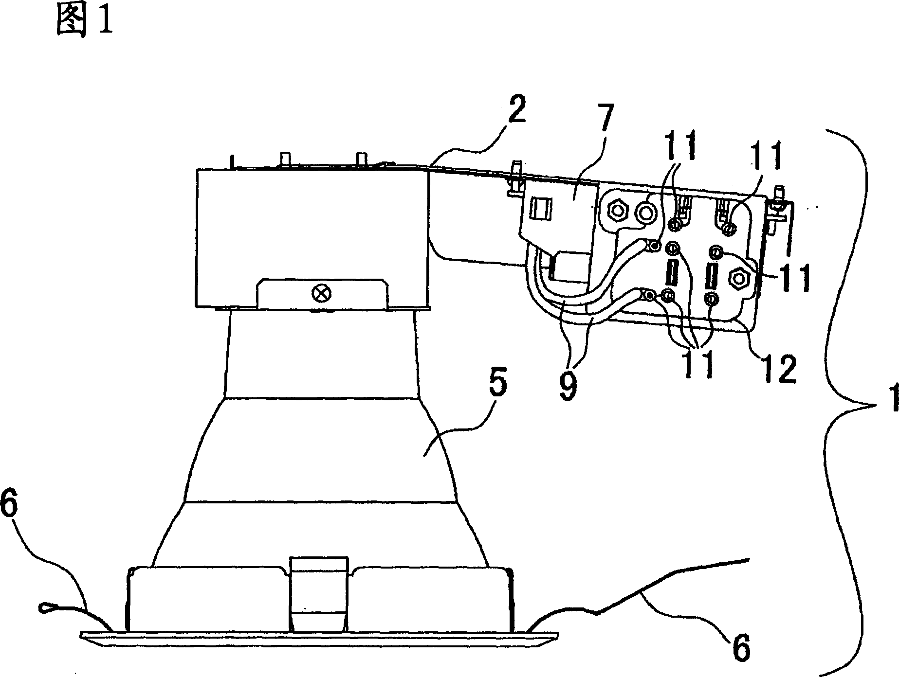
[0018] FIG. 1 shows a lighting fixture according to Embodiment 1, and the lighting fixture of FIG. 1 will be described.
[0019] The lighting fixture 1 has: a lighting fixture main body 2, a lamp socket 4 (not shown) mounted on the lighting fixture main body 2 to fix a lamp 3 (not shown), a reflector 5 for reflecting light from the lamp 3, and a reflector 5 disposed on the reflector. The outer peripheral part of the plate 5, the mounting spring 6 fixed on the ceiling, etc., the lighting device 7 connected to the lamp socket 4 by wires, and the lamp 3 is supplied with power through the lamp socket 4, and the power supply line 8 (not shown) for supplying power from the outside. shown in the figure), connected with the above lighting device 7, the electric wire 9 for supplying power to the above lighting device 7, and the wire socket 11 for inserting the grounding wire 10 (not shown) for grounding. The terminal pad 12 on the outer contour of the main body 2 .
[0020] Next, the ...
Embodiment approach 2
[0055] The configuration of the present embodiment reduces the positioning protrusions 20 and the positioning recesses 25 of the first embodiment, and uses the positioning protrusions 20 , the positioning recesses 25 and the ribs 17 to perform positioning of the fixing module 19 .
[0056] FIG. 7 is a diagram showing the terminal board main body 13 and the fixing module 19 in this embodiment, and the same parts as those in the first embodiment are given the same reference numerals and description thereof will be omitted.
[0057] A positioning protrusion 20 is provided on one side surface of the inner wall of the terminal board main body 13 , and two ribs 17 are provided on the bottom surface.
[0058] At this time, the positioning protrusion 20 and the two ribs 17 are arranged so that the wire connection positioning protrusion 20 and the two ribs 17 form a triangle when the terminal board main body 13 is viewed from the opening.
[0059] The fixing block 19 has a positioning ...
Embodiment approach 3
[0062] In the configuration of the present embodiment, the positioning convex portion 20 and the positioning concave portion 25 of the first embodiment are removed, and the fixing module 19 is positioned using the rib 17 .
[0063] FIG. 8 is a diagram showing the terminal board main body 13 and the fixing module 19 in this embodiment, and the same parts as those in the first embodiment are given the same reference numerals and description thereof will be omitted.
[0064] There are three ribs 17 on the bottom surface 16 of the terminal board main body 13, and the three ribs 17 are arranged so that the three ribs 17 connected by wires form a triangle when the terminal board main body 13 is viewed from the opening.
[0065] The fixing module 19 has rib accommodating parts 26 respectively accommodating three ribs 17 of the terminal disc main body 13. Fixed module 19.
[0066] Since the fixing module 19 is clamped by the two ribs 17, it is restricted and cannot move forward, back...
PUM
 Abstract
Description
Claims
Application Information