Robot monitoring system

A technology for monitoring systems and robots, applied in general control systems, control/regulation systems, computer control, etc., to solve problems such as inability to display images that can be observed

Inactive Publication Date: 2007-03-07
FANUC LTD
View PDF3 Cites 23 Cited by
  • Summary
  • Abstract
  • Description
  • Claims
  • Application Information

AI Technical Summary

Problems solved by technology

Therefore, various problems such as positional deviation or interference between the two parts that occur during the operation of the model image may not be displayed as an observable image due to the display conditions (line of sight or drawing format) when they occur.
In this case, especially in the monitoring of responding to various problems by observing the actual movement of the robot as quickly as possible, it may take time to detect the occurrence of a problem and to identify the cause, and it is difficult to quickly implement appropriate measures.

Method used


Image

  • Robot monitoring system
  • Robot monitoring system
  • Robot monitoring system

Examples


Embodiment Construction

[0022] Embodiments of the present invention will be described in detail below with reference to the drawings. In the drawings, the same reference symbols are assigned to the same or similar components.

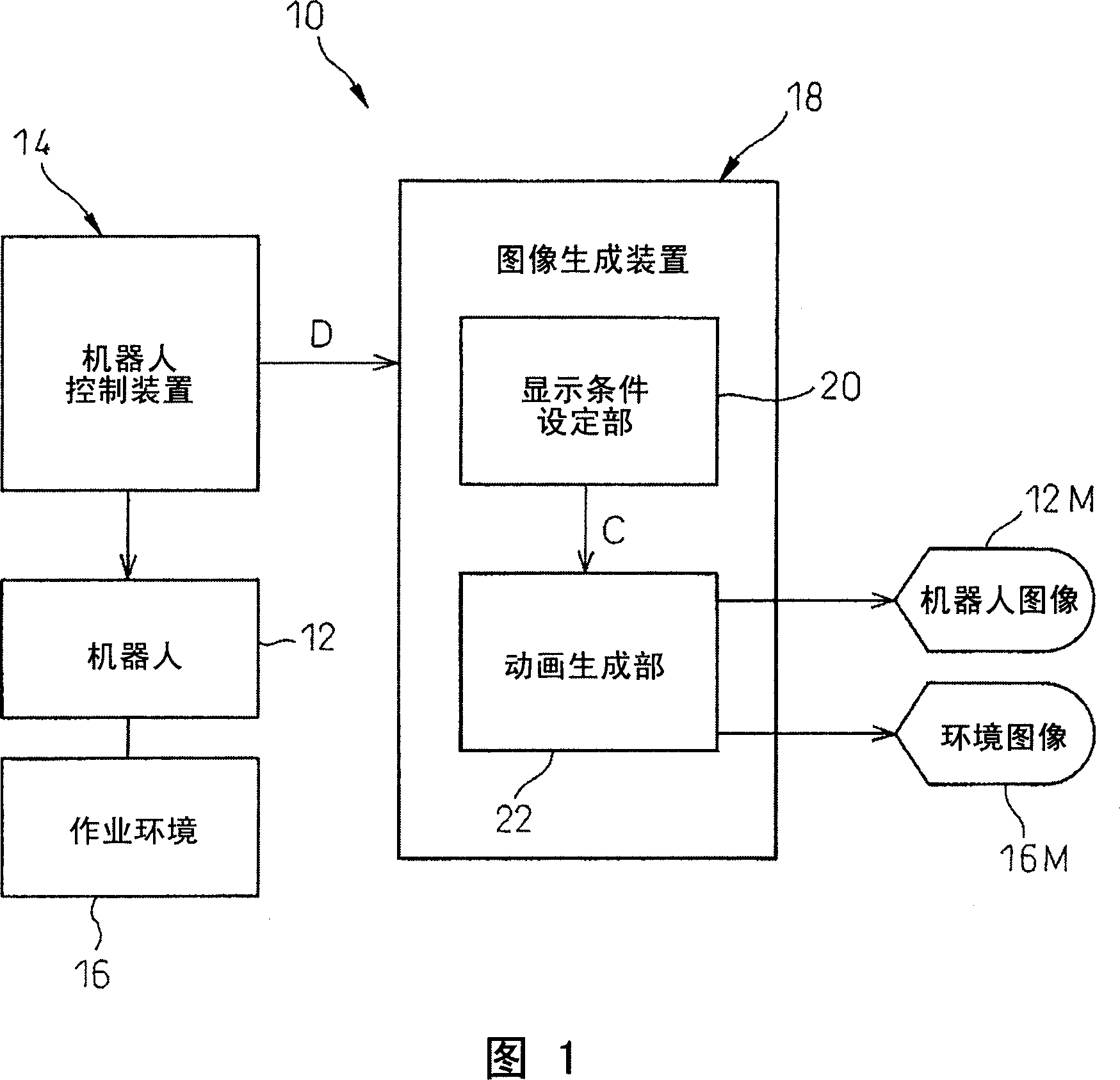
[0023] Referring to the drawings, FIG. 1 is a functional block diagram showing the basic structure of a robot monitoring system 10 in the present invention. The robot monitoring system 10 has: a robot control device 14 that controls the robot 12; and an image generating device 18 that generates a three-dimensional model image of the robot 12 and the working environment 16 of the robot 12 according to the robot control-related information D obtained from the robot control device 14. 12M and 16M are generated as animations corresponding to the actual movement of the robot 12 . The image generating device 18 has: a display condition setting unit 20, which can changeably set display conditions C including at least one of a line of sight and a drawing form of animation representin...


PUM


Abstract

A robot monitoring system including a robot controller for controlling a robot ; and an image generating apparatus for generating, based on robot-control related information obtained from the robot controller, a three-dimensional model image showing the robot and a working environment thereof as a dynamic image corresponding to an actual motion of the robot. The image generating apparatus includes a display-condition setting section for setting a display condition to be changeable corresponding to the actual motion of the robot, the display condition including at least one of a line of sight and a drawing type; and a dynamic-image generating section for generating the dynamic image to be replaceable according to a change, occurring corresponding to the actual motion of the robot, in the display condition. The robot-control related information, obtained from the robot controller, includes an operation program for commanding a certain operation to the robot. A command relating to a change in the display condition is described in the operation program.

Description

technical field [0001] The invention relates to a robot monitoring system, in particular to a robot monitoring system using a three-dimensional model image of a robot. Background technique [0002] Robots, especially industrial robots, operate according to specific work programs (ie, task programs). Appropriately select various types of work programs corresponding to the type of tool (i.e., robot hand-operated device) mounted on the robot, the type of workpiece to be worked on, the content of the work, etc., and give it to the robot, so that one robot can execute Various jobs. In a production system using such a robot, a system is provided that displays a robot and a model image of the robot's work environment on a display as an animation corresponding to the actual movement of the robot based on information related to robot control such as a work program that controls the robot. device, so that the simulation or monitoring of the robot's action state can be performed. ...

Claims


Application Information

Patent Timeline
Patent Type & Authority Applications(China)
IPC IPC(8): B25J9/16B25J13/00G05B19/4069
CPCB25J9/1671B25J9/1674
Inventor 长塚嘉治小林博彦
Owner FANUC LTD
Why Eureka
Try Eureka