Circuit for limiting the input voltage on a pin of an integrated circuit

A technology of circuit devices and integrated circuits, applied in the field of circuit devices, can solve problems such as weakening the functions of integrated circuits 1, and achieve the effect of preventing damage

Inactive Publication Date: 2007-03-07
PATENT TREUHAND GESELLSCHAFT FUR ELECTRIC GLUEHLAMPEN MBH
View PDF0 Cites 0 Cited by
  • Summary
  • Abstract
  • Description
  • Claims
  • Application Information

AI Technical Summary

Problems solved by technology

A significant disadvantage of this arrangement can be seen in the fact that the high leakage current of the Schottky diode 3 impairs the functioning of the integrated circuit 1 in the case of very sensitive conditions of the integrated circuit 1, especially at elevated temperatures

Method used


Image

  • Circuit for limiting the input voltage on a pin of an integrated circuit
  • Circuit for limiting the input voltage on a pin of an integrated circuit

Examples


Embodiment Construction

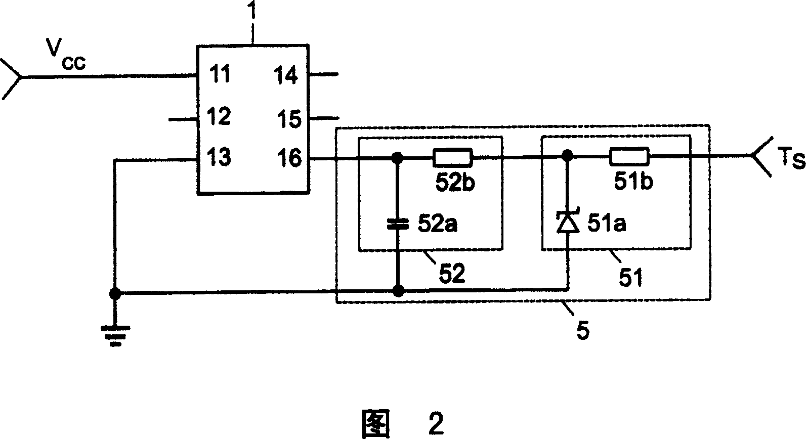
[0016] Figure 2 shows a schematic diagram of an electrical circuit, which in this exemplary embodiment is arranged in an electronic ballast designed to control or operate an electric lamp. The integrated circuit 1 is supplied with the supply voltage V via the first terminal pin 11 ∝ . In this exemplary embodiment, integrated circuit 1 has six terminal pins 11 to 16 , the electrical connection of integrated circuit 1 to ground potential being provided at terminal pin 13 . In the exemplary embodiment shown in FIG. 2 , the integrated circuit 1 is electrically connected via pins 16 to a transient generator, which may be, for example, a lamp. The transient generator can generate transients through switching operations and these transients can be transmitted to pin 16 . In order to be able to prevent these transients from being transmitted in this way to the pin 16 and thus to the integrated circuit 1, the circuit arrangement 5 according to the invention for limiting the input vol...


PUM


Abstract

The arrangement (5) is designed as a gradual limiter and filter circuit to limit that input voltage at a connection pin (16) of an IC (1). The arrangment is electrically connected to the connection pin(16).

Description

technical field [0001] The invention relates to a circuit arrangement for limiting an input voltage at a pin of an integrated circuit to which the circuit arrangement is electrically connected. Background technique [0002] A voltage within a certain range of values ​​should normally be applied to the pins of an integrated circuit. However, such an operating state in which a voltage value outside the predetermined value range occurs at the pin of the integrated circuit occurs repeatedly. Those operating states in which these voltage windows are exceeded often lead to erroneous responses or malfunctions in the integrated circuit. In a conventional integrated circuit, the peak value of the applied voltage should be no more than 0.3V above the positive supply voltage and no less than -0.3V below the negative supply voltage. Furthermore, the minimum or maximum voltage value is often defined by the potential around the supply voltage. Depending on the application of the integr...

Claims


Application Information

Patent Timeline
IPC IPC(8): H02H9/04H05B41/14H05B41/285H05B41/298
CPCH01L27/0248H02H9/046
Inventor M·赫克曼T·赛格蒙特
Owner PATENT TREUHAND GESELLSCHAFT FUR ELECTRIC GLUEHLAMPEN MBH
Why Eureka
Try Eureka