Welding tool for copper and copper alloy stirring friction welding
A technology of friction stir and copper alloy, applied in welding equipment, manufacturing tools, non-electric welding equipment, etc., can solve the problems of unfavorable welding tool structure size modification, waste of high melting point materials, and poor practicability of welding tools, so as to save high melting point materials , Reduce processing and manufacturing costs, and facilitate size modification
- Summary
- Abstract
- Description
- Claims
- Application Information
AI Technical Summary
Problems solved by technology
Method used
Image

Examples
specific Embodiment approach 1
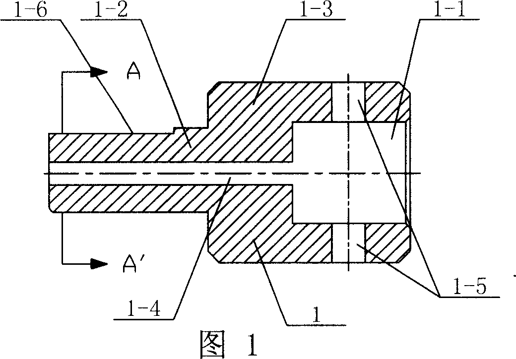
[0011] Specific Embodiment 1: This embodiment is described with reference to FIG. 1 , FIG. 3 , and FIG. 5 . The welding tool in this embodiment has a split structure and consists of a clamping body 1 , a stirring head 2 and a screw 3 . The clamping body 1 is composed of two coaxial cylinders on the left and right sides, and the diameter of the left cylinder 1-2 is smaller than the diameter of the right cylinder 1-3. The right cylinder 1-3 is provided with a cavity 1-1 for putting into the stirring head 2, and the upper and lower walls of the cavity 1-1 of the right cylinder 1-3 are provided with an axis perpendicular to the axis of the right cylinder 1-3. The threaded through hole 1-5, the stirring head 2 is a cylinder, and an outwardly protruding stirring pin 2-1 is arranged in the middle part of the right end of the stirring head 2, which is used for stirring and friction during welding, and the left end of the stirring head 2 Inserted in the cavity 1-1, the screw 3 is screw...
specific Embodiment approach 2
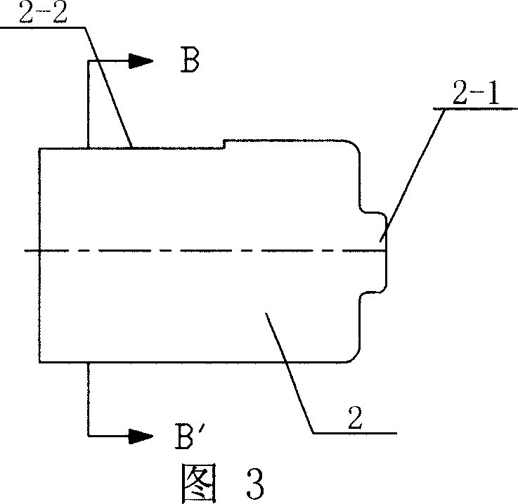
[0012] Specific embodiment two: illustrate this embodiment in conjunction with Fig. 3, Fig. 4, Fig. 5, the top end of the left side outer end face of the mixing head 2 of this embodiment is provided with a platform 2-2 along the axial direction, the size of platform 2-2 Determined according to the length of the stirring head 2 that needs to be exposed and the size of the cavity 1-1 where the holder 1 is placed in the stirring head 2, the left end of the stirring head 2 where the platform 2-2 is located is placed in the cavity of the holder 1. In the cavity 1-1, the tail end of the screw 3 is in close contact with the platform 2-2, so as to avoid axial and circumferential movement between the stirring head 2 and the holding body 1.
specific Embodiment approach 3
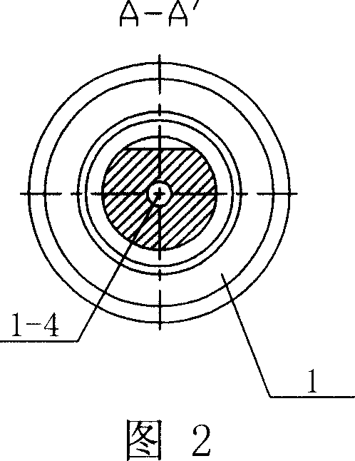
[0013] Specific Embodiment Three: This embodiment is described in conjunction with Fig. 1, Fig. 2 and Fig. 5. A platform 1- 6. It is used for fixing the clamping body 1 on the running machine.
PUM
| Property | Measurement | Unit |
|---|---|---|
| Diameter | aaaaa | aaaaa |
| Length | aaaaa | aaaaa |
Abstract
Description
Claims
Application Information