
Visual cable detection device with adjustable detection space closed shooting distance

A technology of shooting distance and detection space, applied in the field of visual cable detection devices, can solve the problems that video and images cannot meet the needs of post-processing, it is difficult to promote the intelligent detection process of bridge cables, and it is difficult to propose an applicability post-processing algorithm. The effect of improving the ability to resist external interference, simple structure and reducing detection cost

Active Publication Date: 2021-02-26
上海能莹实业有限公司
View PDF15 Cites 2 Cited by
  • Summary
  • Abstract
  • Description
  • Claims
  • Application Information

AI Technical Summary

Problems solved by technology

[0003] Videos and images acquired by common bridge cable detection devices are difficult to meet the needs of post-processing
The combination of image acquisition and post-processing is not fully considered. The background of the captured video image is complex, and there may be some light problems due to sunlight and other reasons during the shooting process. Moreover, because the image acquisition device is integrated with the cable climbing device, the video captured by the camera is often affected. Vibration caused by motor vibration
These all add unnecessary burdens and influences of unknown factors to image processing operations such as cable surface area extraction, multi-channel video stitching, and defect location measurement in the later stage, making it difficult to propose a post-processing algorithm with strong applicability, and it is difficult to promote the development of bridge cables. Intelligent detection process
In addition, the current cable detection device mainly relies on the automatic zoom of the camera for cables of different diameters, and the effective detection range of the cable diameter is small

Method used


Image

  • Visual cable detection device with adjustable detection space closed shooting distance
  • Visual cable detection device with adjustable detection space closed shooting distance
  • Visual cable detection device with adjustable detection space closed shooting distance

Examples


Embodiment Construction

[0033] The following will clearly and completely describe the technical solutions in the embodiments of the present invention with reference to the accompanying drawings in the embodiments of the present invention. Obviously, the described embodiments are only some, not all, embodiments of the present invention. Based on the embodiments of the present invention, all other embodiments obtained by persons of ordinary skill in the art without making creative efforts belong to the protection scope of the present invention.

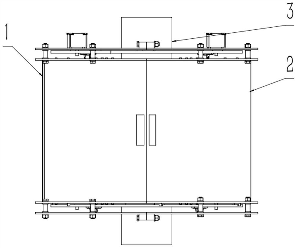
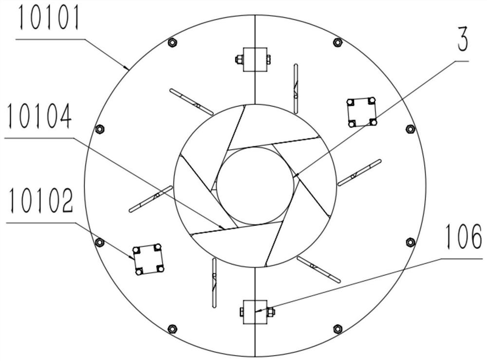
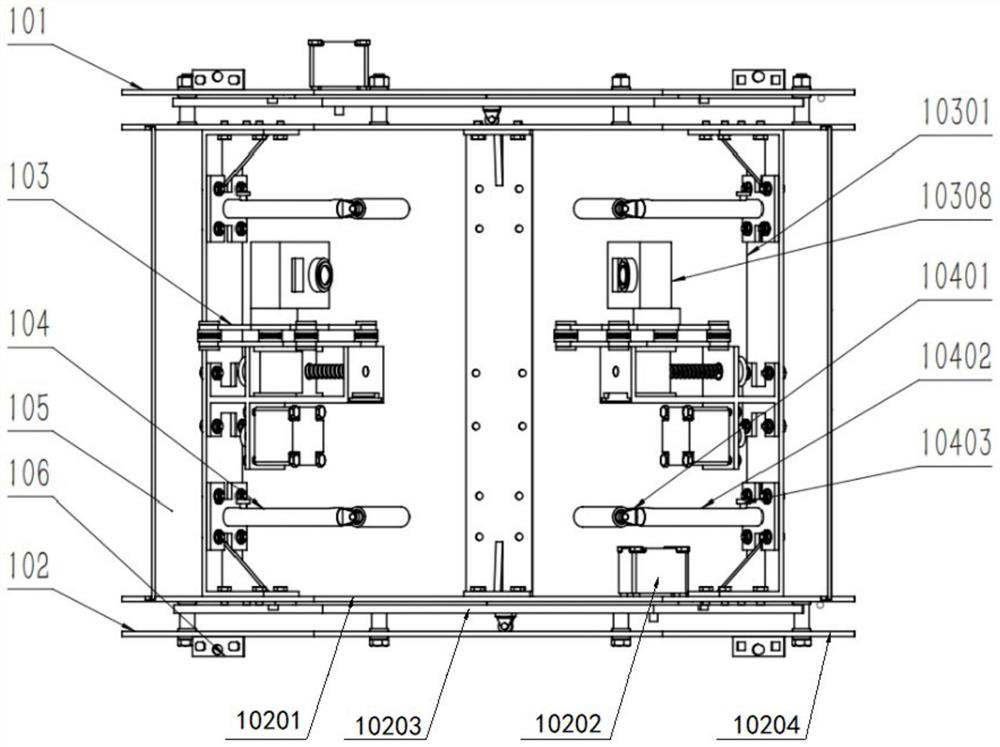
[0034] as attached figure 1 to attach Figure 7As shown: the present invention provides a visual cable detection device with adjustable shooting distance for detecting space confinement, including two symmetrical systems, left system 1 and right system 2, and left system 1 is provided with an upper rotary opening and closing system 101 and a lower Rotary opening and closing system 102, between the upper rotating opening and closing system 101 and the lower ro...


PUM


Abstract

The invention relates to the technical field of cable detection, in particular to a visual cable detection device with an adjustable detection space closed shooting distance, which comprises two symmetrical systems, namely a left side system and a right side system; wherein the left side system is provided with an upper rotary opening and closing system and a lower rotary opening and closing system; a distance-adjustable shooting system is arranged between the upper rotary opening and closing system and the lower rotary opening and closing system, pressing mechanisms are arranged between the shooting system and the upper rotary opening and closing system and between the shooting system and the lower rotary opening and closing system respectively, shading structures are arranged on the outer sides of the symmetrical systems, and connecting structures are arranged on the upper sides and the lower sides of the symmetrical systems. The device is built mostly with bolt connection, so that the structure is simple, maintenance is convenient, the production and manufacturing cost is low, and good economic benefits can be brought; the bolts are rigidly connected with the set screws and thelike, so that the stability of the detection device in the detection process is ensured, and the external interference resistance of the detection device is improved.

Description

technical field [0001] The invention relates to the technical field of cable detection, in particular to a visual cable detection device with adjustable shooting distance in a closed detection space. Background technique [0002] Cable-stayed bridges are more and more used in transportation because of their beautiful appearance, low cost and good earthquake resistance. The cable is one of the main stress components of the cable-stayed bridge and the lifeline of the whole bridge. However, due to the long-term exposure of the cable to the air, the impact of wind, sun, and rain erosion, the surface protective layer of the cable and even the steel wire inside the cable will be damaged to varying degrees. When it is serious, it will directly affect the normal use of the bridge and endanger the safety of people's lives and property. In order to monitor the state of the cable, detect damage as early as possible, intervene in time, reduce maintenance costs, and avoid more serious ...

Claims


Application Information

Patent Timeline
Patent Type & Authority Applications(China)
IPC IPC(8): G01N21/01G01N21/952
CPCG01N21/01G01N21/952
Inventor 胡永彪孙宏斐夏晓华陆小虎鲁航杨泽文
Owner 上海能莹实业有限公司
Learn More