Liquid crystal filling device and method

A filling device and filling method technology, applied in nonlinear optics, instruments, optics, etc., can solve the problems of poor uniformity and uneven display of the display panel, and achieve the effect of accurate spraying amount

Inactive Publication Date: 2007-03-14
UNITED MICRODISPLAY OPTRONICS CORP
View PDF0 Cites 4 Cited by
  • Summary
  • Abstract
  • Description
  • Claims
  • Application Information

AI Technical Summary

Problems solved by technology

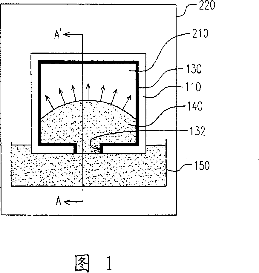
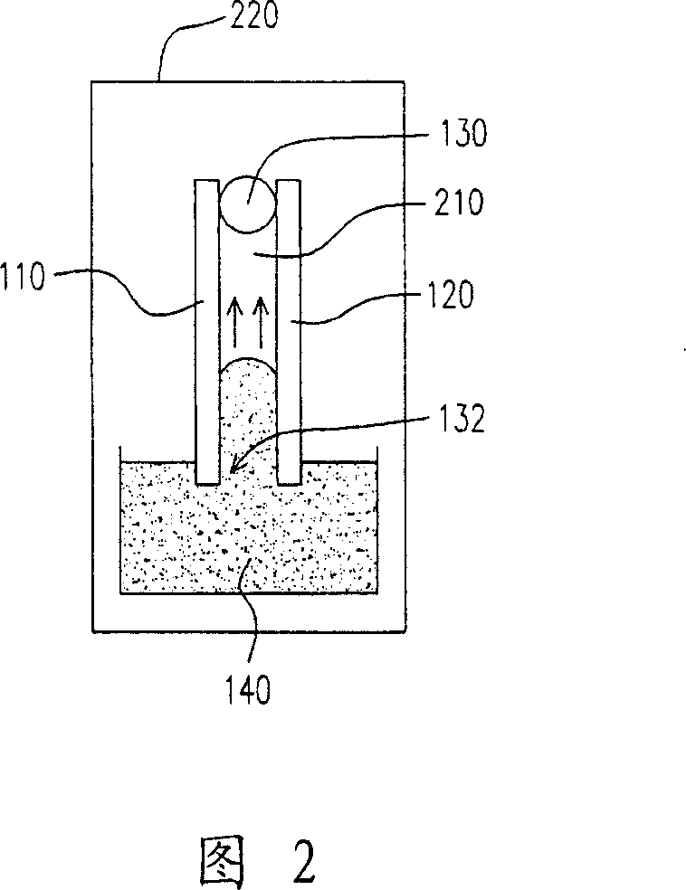
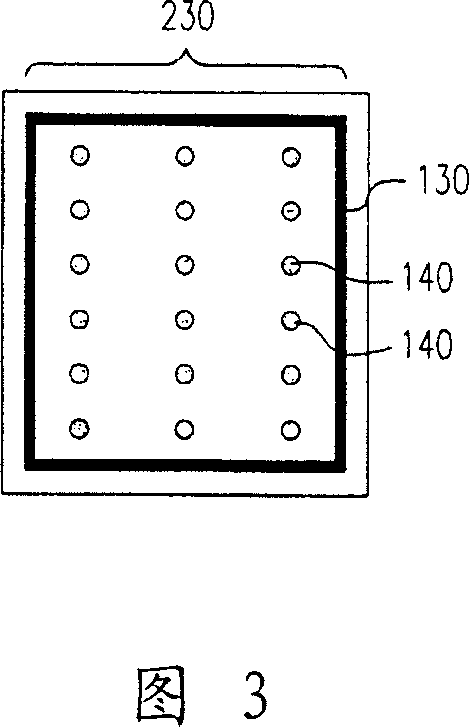
[0006] Although the above-mentioned liquid crystal dropping method has a faster liquid crystal introduction speed, because this method is to drop the liquid crystal material 140 in the display area 230 in a point-like manner, it is easy to make the filled liquid crystal material 140 on the substrate. 110. The uniformity between the opposite substrate 120 and the sealant 130 is not good, and it is easy to produce dot-like or strip-like display unevenness (mura) on the liquid crystal display panel

Method used


Image

  • Liquid crystal filling device and method
  • Liquid crystal filling device and method
  • Liquid crystal filling device and method

Examples


Embodiment Construction

[0050] FIG. 5 is a schematic diagram of a liquid crystal filling device according to a preferred embodiment of the present invention. The liquid crystal filling device 300 mainly includes a stage 310 and a jet print head module 330, wherein the stage 310 is suitable for carrying the substrate 110, and the print head module 330 is arranged above the stage 310, and the jet print head module 330 It is suitable for spraying the liquid crystal material 140 on the substrate 110 through the relative movement between it and the stage 310 .

[0051] In a preferred embodiment, the liquid crystal filling device 300 may also have a frame body 320 , wherein at least one sliding rail 325 is provided on the frame body 320 . The spray head module 330 is disposed on the frame body 320 and can slide relative to the platform 310 via the slide rail 325 . Of course, in this embodiment, for example, the sliding rail 325 can also be arranged at the bottom of the carrier 310 , so that the carrier 31...


PUM


Abstract

The LC filling device for forming LC layer on substrate comprises a carrying stage for supporting substrate and a spray module above the stage fit to spray LC material to substrate.

Description

technical field [0001] The invention relates to a liquid crystal panel manufacturing equipment and method, in particular to a liquid crystal filling equipment and method. Background technique [0002] Among various types of displays, Liquid Crystal Display (LCD) has gradually become the mainstream of the market due to its superior characteristics such as high image quality, good space utilization efficiency, low power consumption, and no radiation. The liquid crystal panel of the liquid crystal display mainly includes a substrate, an opposite substrate, a liquid crystal material, and a sealant, wherein the liquid crystal material is sealed between the substrate and the opposite substrate through the sealant. Generally speaking, in the manufacturing process of the liquid crystal display panel, a liquid crystal introduction process is usually required to fill and seal the liquid crystal material between the substrate, the opposite substrate and the sealant. Therefore, the liq...

Claims


Application Information

Patent Timeline
Patent Type & Authority Applications(China)
IPC IPC(8): G02F1/1341
Inventor 周志谦
Owner UNITED MICRODISPLAY OPTRONICS CORP
Why Eureka
Try Eureka