Internal combustion engine having fuel mixing means installed in intake port

A technology for mixing components and internal combustion engines, which is applied to internal combustion piston engines, building components, combustion engines, etc., and can solve problems such as inability to mix fuel and air, and disappearance of eddy or turbulent flow.

Inactive Publication Date: 2007-03-14
BO KWANG IND
View PDF0 Cites 4 Cited by
  • Summary
  • Abstract
  • Description
  • Claims
  • Application Information

AI Technical Summary

Problems solved by technology

[0005] However, since this conventional swirl unit is arranged in the intake manifold or between the intake manifold and the air cleaner, before the air passing through the swirl unit reaches the fuel injector or the combustion chamber, it will and make the vortex or turbulence disappear a lot
Therefore, the fuel and air cannot be mixed efficiently, and the mixture of fuel and air supplied to the combustion chamber cannot form swirl or turbulence in the combustion chamber

Method used


Image

  • Internal combustion engine having fuel mixing means installed in intake port
  • Internal combustion engine having fuel mixing means installed in intake port
  • Internal combustion engine having fuel mixing means installed in intake port

Examples


Embodiment Construction

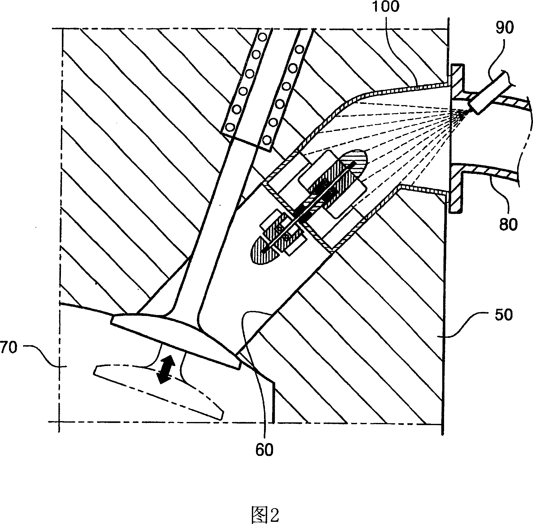
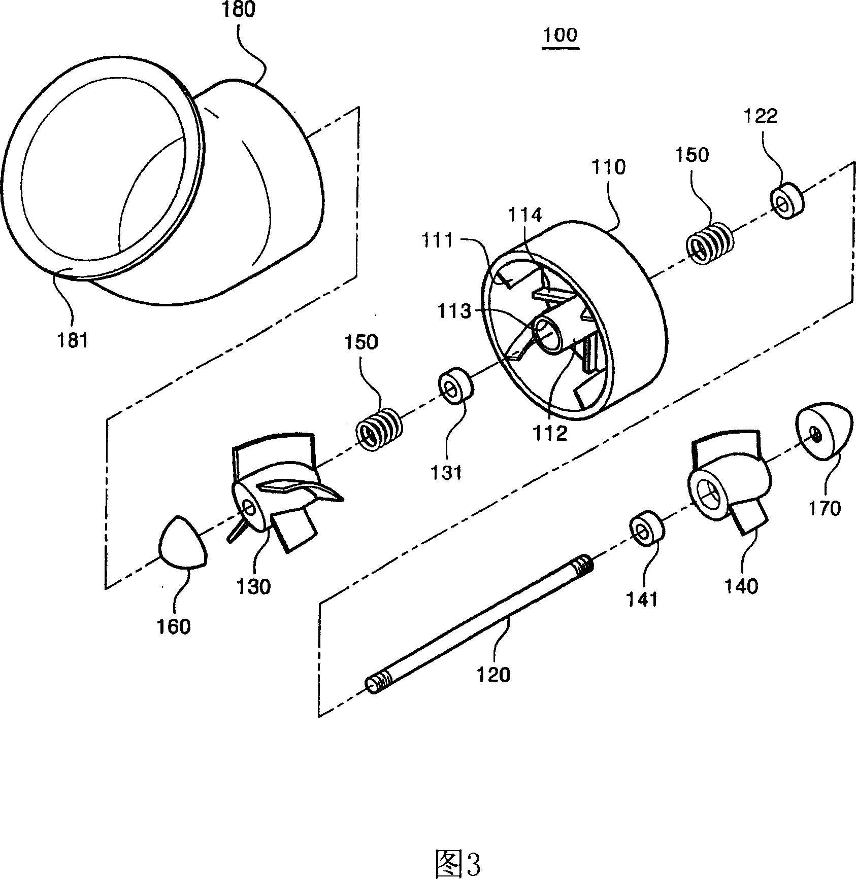
[0031] 2 is a sectional view of an intake port of an internal combustion engine according to a first embodiment of the present invention, FIG. 3 is an exploded perspective view of a fuel mixing member of the embodiment shown in FIG. 2 , and FIG. 4 shows the embodiment shown in FIG. 2 The perspective view of the assembled state of the fuel mixing member, and Fig. 5 is a cross-sectional view taken along line A-A of Fig. 4 .

[0032] The internal combustion engine of the present embodiment includes a fuel mixing member 100 fixedly inserted into an intake port 60 formed in the cylinder head 50 and serving as a passage for supplying a mixture of fuel and air into the combustion chamber 70 .

[0033] The fuel mixing member 100 includes a hollow cylindrical support ring 110 which is inserted into the intake passage 60 . Since the conventional cylinder head is made by casting, it is difficult to cut the intake port or change the shape of the intake port.

[0034] In consideration of ...


PUM


Abstract

The present invention relates to an internal combustion engine, and more particularly, to an internal combustion having improved performance by promoting mixing of fuel and air using a fuel mixing means installed at an intake port to improve the flow property of the mixture introduced into a combustion chamber. In an internal combustion engine according to the present invention, a fuel mixing means is installed at an intake port for use in supplying a mixture of fuel and air into a combustion chamber. The fuel mixing means is provided with a stream-disturbing body having a plurality of vanes for disturbing a stream passing through the intake port. The stream-disturbing body is installed rotatably in the intake port to generate a vortex or turbulence so that fuel and air are mixed uniformly and then supplied into the combustion chamber.

Description

technical field [0001] The present invention relates to an internal combustion engine, and more particularly, to an internal combustion engine having a fuel mixing member installed in an intake passage. The present invention relates to an internal combustion engine in which the mixing of fuel and air to be supplied into a combustion chamber is promoted by a fuel mixing member and the fluidity of flow supplied into the combustion chamber is improved, thereby improving performance. Background technique [0002] FIG. 1 is a sectional view of an intake port formed in a cylinder head of a conventional internal combustion engine. [0003] An intake port 16 is formed in the cylinder head 15 to communicate with a combustion chamber 17 so as to supply a mixture of fuel and air into the combustion chamber. An intake manifold 18 is coupled to the inlet of intake passage 16 . Particularly in the case of a gasoline engine, a fuel injector 19 is mounted on the intake manifold side, at t...

Claims


Application Information

Patent Timeline
IPC IPC(8): F02B31/00
CPCY02T10/146Y02T10/12E05F15/673E05F15/684E06B2009/1594
Inventor 洪英杓
Owner BO KWANG IND
Why Eureka
Try Eureka