Method and device for filling a container with a predetermined quantity of fluid and related filling machine

A kind of filling equipment and pre-measurement technology, applied in liquid filling, liquid bottling, liquid treatment, etc.

Inactive Publication Date: 2007-03-21
西德尔分享公司
View PDF0 Cites 14 Cited by
  • Summary
  • Abstract
  • Description
  • Claims
  • Application Information

AI Technical Summary

Problems solved by technology

In this case, the position control signal can cause the wrong amount of fluid to be delivered

Method used


Image

  • Method and device for filling a container with a predetermined quantity of fluid and related filling machine
  • Method and device for filling a container with a predetermined quantity of fluid and related filling machine
  • Method and device for filling a container with a predetermined quantity of fluid and related filling machine

Examples


Embodiment Construction

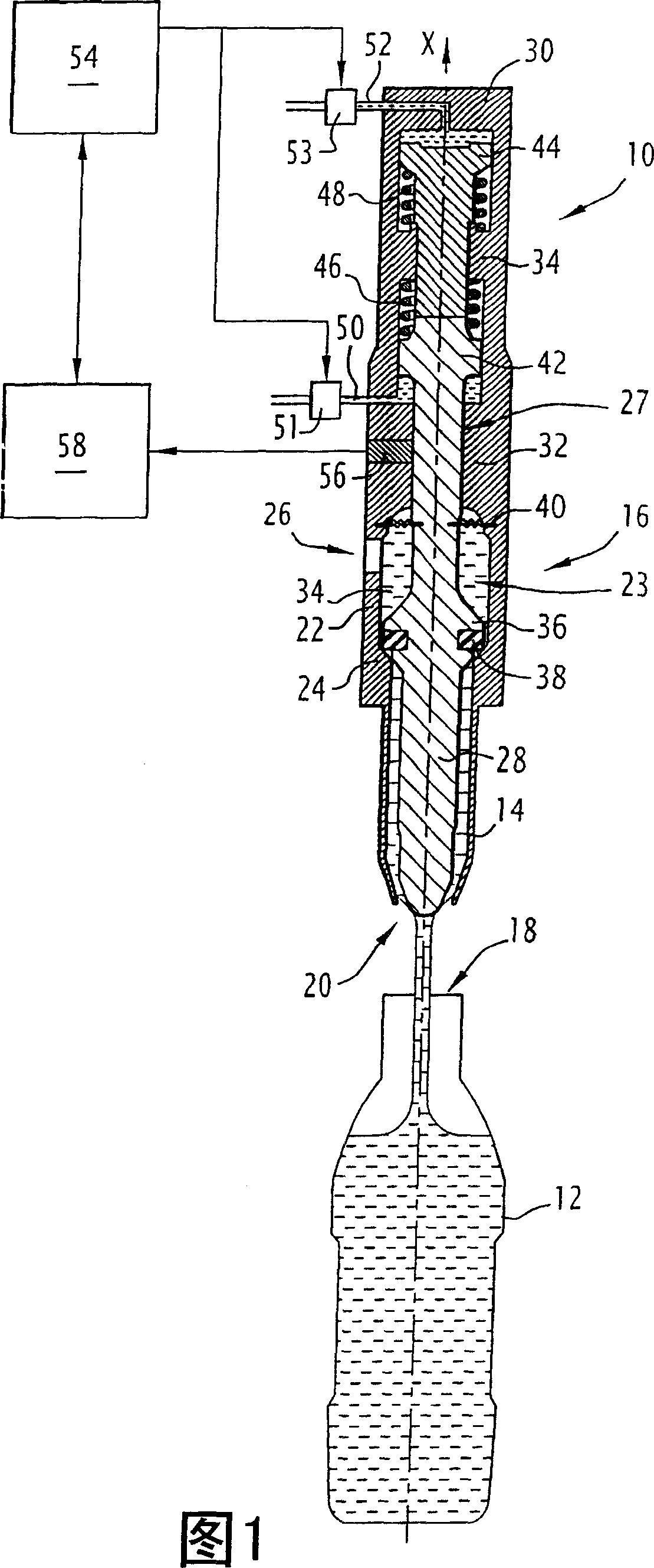
[0016] In the following description, the terms "above", "below", "high", "low", etc. refer to a vertical axis X along which the container and the filling device generally extend and along which the fluid flows. A straight axis X flows from the filling device to the container. The container is located below the filling device.

[0017] The filling device shown in FIG. 1 is denoted by reference number 10 . It is to fill a container 12, in this case a bottle, with a fluid which may be water or any type of liquid.

[0018] The filling device 10 comprises a nozzle 14 for delivering a flow of fluid along a vertical axis X into the container 12 , and a valve 16 for controlling the flow of fluid through the nozzle 14 .

[0019] The nozzle 14 is in the shape of a vertical tube which is located above the opening 18 of the container 12 . The diameter of the tube decreases near its lower end 20 , which faces the opening 18 .

[0020] Valve 16 comprises an outer housing 22 extending up...


PUM


Abstract

An apparatus is disclosed comprising a nozzle (14) for delivering a fluid flow into a container (12); a valve (16) comprising a movable valve member (27) for controlling said fluid flow; means (54) for said movable valve member (27) to send a position control signal whereby said movable valve member (27) will follow a desired displacement versus time profile which will be delivered into said container (12) The amount of fluid is adjusted to a predetermined amount. The apparatus also includes detecting means (56) for detecting points of the actual displacement versus time curve followed by the movable valve member (27) in response to detection of the position control signal; and comparing means (58) for comparing Corresponding points on the detected point and the expected displacement versus time curve.

Description

technical field [0001] The present invention relates to a method and apparatus for filling containers, and a filling machine. Background technique [0002] It is known to fill a container with a predetermined amount of fluid using an apparatus comprising a nozzle for delivering a fluid flow into the container and a valve comprising a movable valve member for controlling the fluid flow. [0003] Known methods implemented using such devices include the step of sending a position control signal to the movable valve member so that said movable valve member will follow a desired displacement versus time profile which adjusts the amount of fluid delivered into the container to a predetermined amount. [0004] This method is disclosed, for example, in Japanese Patent Laid-Open Document No. JP-A-9-156697. [0005] The expected displacement versus time profile of the valve member is determined by testing, which is often done during the course of calibrating the equipment. A positi...

Claims


Application Information

Patent Timeline
Patent Type & Authority Applications(China)
IPC IPC(8): B67C3/26B67C3/28B67D7/52B67D7/30B67D7/36
CPCB65B3/36B67C3/02B67C3/286B67C3/007B29C2049/5831
Inventor 山德罗·蒙塔沃奇弗朗哥·穆蒂
Owner 西德尔分享公司
Why Eureka
Try Eureka