Production process of silicon single crystal

一种硅单晶、熔融硅的技术,应用在单晶生长、单晶生长、化学仪器和方法等方向,能够解决适应性及应用性差、成本上拉晶体次数指数增加等问题

Inactive Publication Date: 2007-03-21
SILTRONIC AG
View PDF7 Cites 11 Cited by
  • Summary
  • Abstract
  • Description
  • Claims
  • Application Information

AI Technical Summary

Problems solved by technology

However, as shown in Reference 3, if the quality standard of the crystal is changed, the crystal growth furnace is replaced, components in the furnace such as insulation and heaters are changed, and the melting amount of raw materials is increased, even without the aforementioned circumstances, if the furnace body is aging or due to The temperature environment in the furnace changes due to the degradation of the furnace parts and the change of the heating environment, so for the factors of component degradation and product deterioration, the adjustment operation of the irritating operating parameters still needs to be repeated several times
[0005] In addition, the recent expansion of silicon single crystals from 8 inches to 12 inches involves a proportional expansion of the furnace body, resulting in an exponential increase in cost and the number of times the crystal needs to be pulled up to adjust the oxygen concentration in the silicon single crystal
Therefore, the adaptability and applicability of the traditional trial and error method to new quality standards and changes in the operating environment are very poor

Method used


Image

  • Production process of silicon single crystal
  • Production process of silicon single crystal
  • Production process of silicon single crystal

Examples


Embodiment 1

[0100] Embodiment 1 corresponds to claims 1 and 3 .

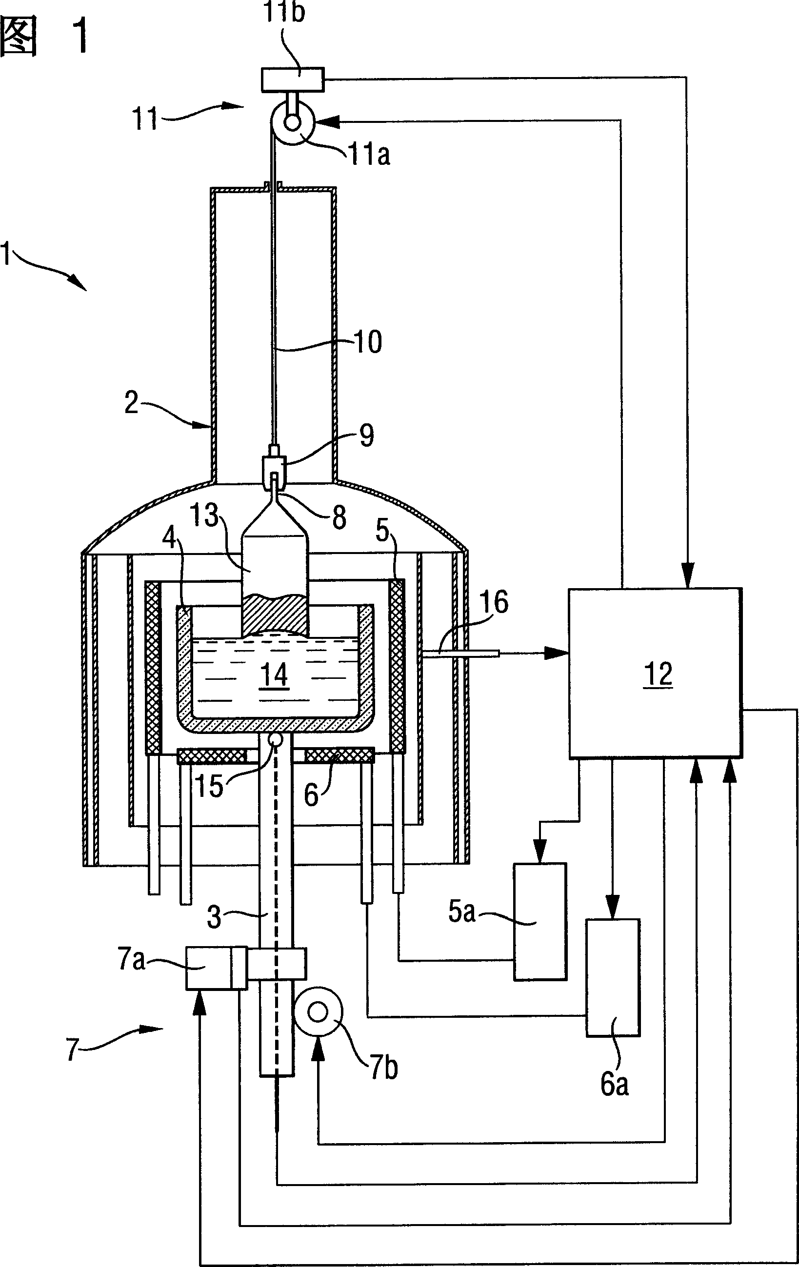
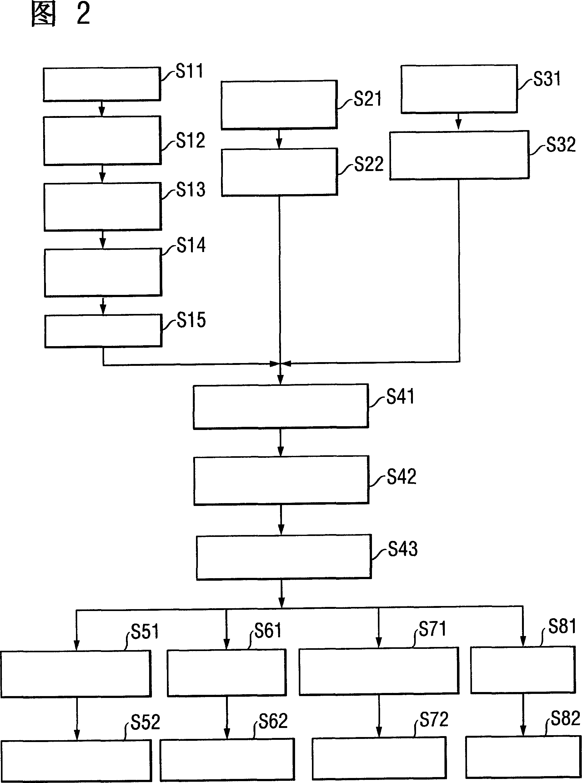
[0101]Grow a 12-inch crystal in the same crystal pulling furnace and furnace assembly as Comparative Example 1, so that the oxygen concentration in the crystal becomes 8.0×10E uniformly 17 (atoms / cubic centimeter), the crucible temperature was controlled by changing the crucible rotation speed during crystal growth. Specifically, in the initial stage of single crystal pull-up, the rotation speed of the crucible is relatively low, and in the later stage of growth, the rotation speed is increased or decreased according to the flowchart shown in FIG. 2 . The respective functions F, G and H for oxygen concentration used within governing equation (1) have the following form:

[0102] F(Ω)=Ω 0.5

[0103] G(T)=T+g Equation (7)

[0104] H(β)=β -1

[0105] The constants A, B and g are determined by the operating conditions of Example 1 and the oxygen concentration of the actually obtained crystals by the least square method. ...

Embodiment 2

[0109] Embodiment 2 corresponds to claims 2 and 3 .

[0110] In Example 2, a 12-inch crystal was grown in the same crystal pulling furnace and hot zone as Comparative Example 1, so that the oxygen concentration in the crystal was evenly changed to 8.0×10E 17 (atoms / cubic centimeter), as in Example 1, the crucible temperature T is controlled by changing the crucible rotational speed Ω in the crystal growth. Specifically, the crucible rotation speed Ω is kept low at the initial stage of single crystal pull-up, and the rotation speed is increased or decreased according to the flow chart shown in FIG. 2 near the later stage of growth. The respective functions F and I of oxygen concentration used in prediction equation (5) have the following form:

[0111] F(Ω)=Ω 0.5

[0112] I(T)=1 / β×Exp(-E / T)

[0113] In addition, the value of E is 24,000 (K), which is an approximate value disclosed in the reference (T, Carberg, J. Electrochem Soc., Vol. 133, No. 9, p. 1940), and the constant...

Embodiment 3

[0117] Embodiment 3 corresponds to claims 3 and 4 .

[0118] In Example 3, at the initial stage of crystal growth, the crucible rotation speed Ω was changed in the same manner as in Example 2, and from the midstream of growth, the crucible rotation speed Ω was fixed at the same rotation speed as in Comparative Example 1 , After that, the change of the crucible temperature T is carried out by adjusting the power supplied to the auxiliary heater 6 . In addition, Equation (5) is used in the prediction equation along with the same functions F and I used in Example 2 and the constants A, B, and E used in Example 2.

[0119] FIG. 6 shows the variation of various operating parameters (rotational speed of the crucible Ω and power supplied to the auxiliary heater 18S) and the temperature T of the crucible. Wherein the crucible rotational speed Ω and the power supplied to the auxiliary heater 18S represent the percentages of the values ​​stated in Comparative Example 1, and the crucibl...


PUM


Abstract

In silicon single crystal growth by the Czochralski method using a quartz crucible, a silicon single crystals with a uniform distribution of oxygen concentration can be produced in high yield without being affected by changes of crystal diameter and initial amount of melt feedstock. The oxygen concentration is adjusted by estimating oxygen concentration during growth on the basis of a relationship among three parameters: crucible rotation rate (Omega), crucible temperature (T), and the ratio (beta) of contact area of molten silicon with the inner wall of the crucible and with atmospheric gas, and by associating the temperature (T) with the ratio (beta) by the function 1 / betaxExp(-E / T) where E is the dissolution energy (E) of quartz into molten silicon to control at least one of the rotation rate (Omega) and temperature (T) to conform the estimated oxygen concentration to a target concentration.

Description

technical field [0001] The present invention relates to the technology of producing silicon single crystal by Czochralski method (Czochralski method, hereinafter referred to as CZ method). Background technique [0002] Oxygen within the silicon wafer has the effect of improving device characteristics by trapping contaminating atoms mixed into the wafer during device production (intrinsic gettering). Therefore, the oxygen concentration in the silicon single crystal should be limited within a given range over the entire area of ​​the crystal fixed diameter part. [0003] Oxygen incorporated into the silicon single crystal originates from the surface of a quartz crucible immersed in molten silicon. In this case, oxygen is mixed into the crystal via the molten silicon. In the traditional CZ method, the problem of non-uniform oxygen concentration along the crystal pull-up direction has occurred. The reasons are considered to be as follows: (1) the contact area of ​​the quartz ...

Claims


Application Information

Patent Timeline
Patent Type & Authority Applications(China)
IPC IPC(8): C30B15/00
CPCC30B29/06C30B15/00Y10S117/916H01L21/20
Inventor 岸田丰竹林圣记玉木辉幸
Owner SILTRONIC AG
Why Eureka
Try Eureka