Engine air filter discharge pipe sealing structure
An engine air filter and pipe sealing technology, applied in the direction of engine components, machines/engines, mechanical equipment, etc., can solve the problems of increasing manufacturing costs, cumbersome manufacturing procedures, increasing the wall thickness of rubber pipes, etc., to ensure tightness and structural implementation. simple effect
Inactive Publication Date: 2007-03-21
CHONGQING CHANGAN AUTOMOBILE CO LTD
View PDF0 Cites 7 Cited by
- Summary
- Abstract
- Description
- Claims
- Application Information
AI Technical Summary
Problems solved by technology
For example: some use rubber, although the softness of the rubber material can meet the sealing performance of the joint, but it is not rigid enough because of its own softness when catering to the engine's rapid acceleration and deceleration conditions. Increase the wall thickness of the rubber tube
Some use engineering plastics, which have enough rigidity, but it is difficult to guarantee the sealing performance of the joints, so the method of changing the wall thickness has to be adopted, which increases the manufacturing cost
There are also rubber-plastic composite structures, although the sealing and rigidity can be taken into account, but the production process is more cumbersome
Method used
View moreImage
Smart ImageViewing Examples

Examples
Embodiment Construction
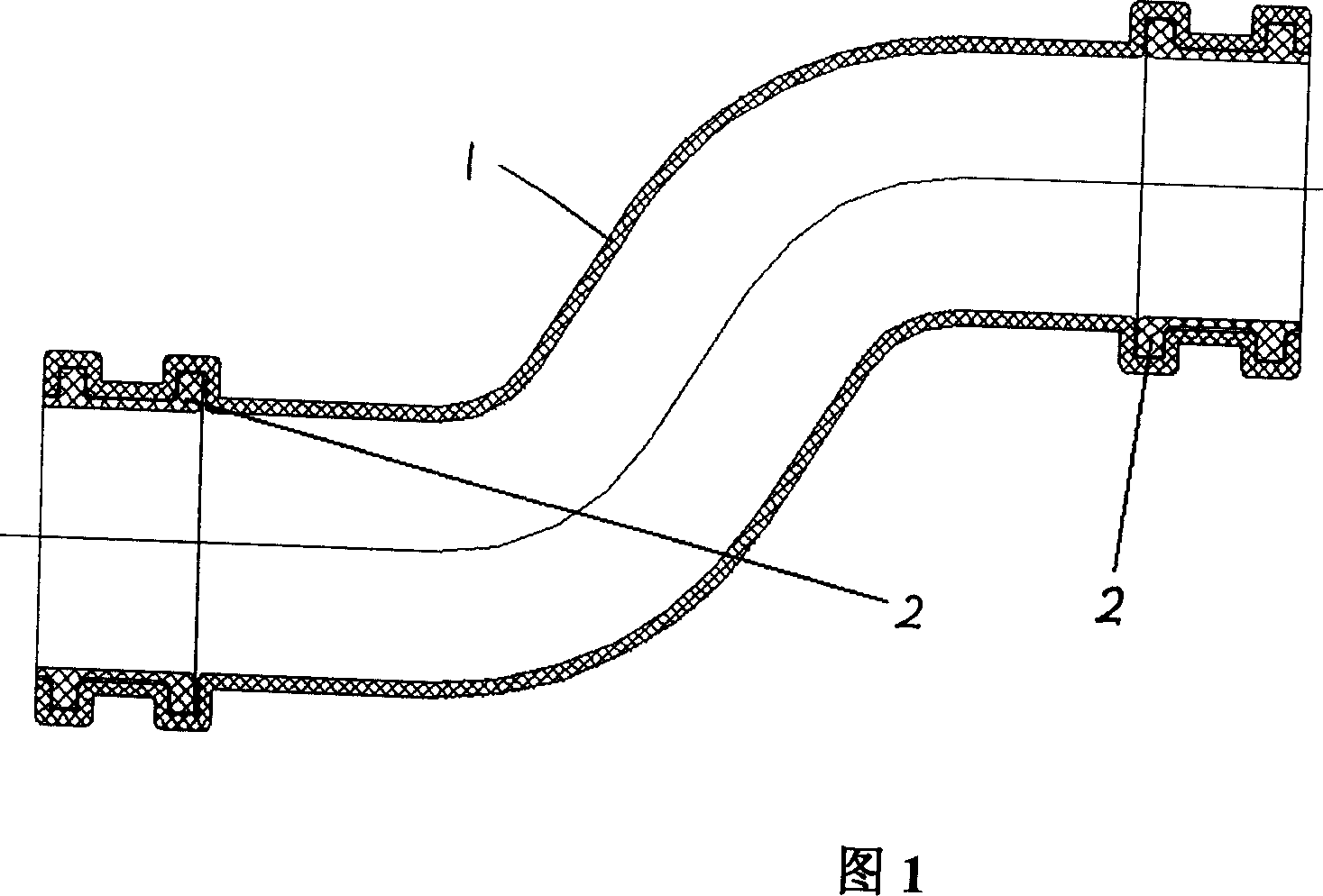
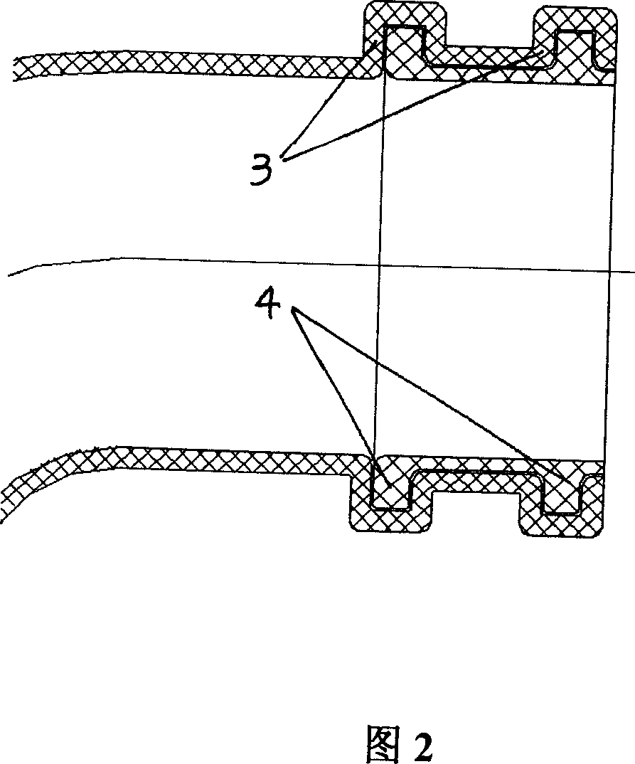
[0010] Referring to Fig. 1, this sealing structure is composed of a pipe body 1 made of engineering plastics and a rubber sealing sleeve 2. It can be seen from Fig. 2 that there are two rings of positioning grooves 3 on the inner wall of the connecting part at both ends of the pipe body 1, and the sealing rubber sleeve There are corresponding two circles of positioning protrusions 4 on the 2, which are stuck in the positioning groove 3.
Login to View More PUM
 Abstract
The present invention relates to an air filter outlet pipe seal structure of engine. It includes pipe self-body made of engineering plastics and sealing rubber cover. On the inner walls of connecting portions of two ends of said pipe self-body several positioning grooves are cut, on the sealing rubber cover several positioning projections which are correspondent to the above-mentioned positioning grooves are set, said invention utilizes the elasticity of rubber to make the rubber cover be fastened into the positioning groove of pipe self-body, so that the pipe self-body and rubber cover can be tightly combined together so as to implement the invented seal structure.
Description
technical field [0001] The invention belongs to the technical field of engines, and in particular relates to a tube sealing structure of an engine. Background technique [0002] At present, the outlet pipe of the air filter on the car engine is mostly made of a single material. For example: some use rubber, although the softness of the rubber material can meet the sealing performance of the joint, but it is not rigid enough because of its own softness when catering to the engine's rapid acceleration and deceleration conditions. Increase the wall thickness of the rubber tube. Some use engineering plastics, which have sufficient rigidity, but the sealing performance of the joints is difficult to guarantee, so the method of changing the wall thickness has to be adopted, which increases the manufacturing cost. There is also a rubber-plastic composite structure, although the sealing and rigidity can be taken into account, but the production process is cu...
Claims
Login to View More Application Information
Patent Timeline
 IPC IPC(8): F02M35/024F16L47/00
Inventor 朱絮飞
Owner CHONGQING CHANGAN AUTOMOBILE CO LTD
Features
- Generate Ideas
- Intellectual Property
- Life Sciences
- Materials
- Tech Scout
- Unparalleled Data Quality
- Higher Quality Content
- 60% Fewer Hallucinations
Learn More Browse by: Latest US Patents, China's latest patents, Technical Efficacy Thesaurus, Application Domain, Technology Topic, Popular Technical Reports.
© 2025 PatSnap. All rights reserved.Legal|Privacy policy|Modern Slavery Act Transparency Statement|Sitemap|About US| Contact US: help@patsnap.com