
Double shoulder tool joint

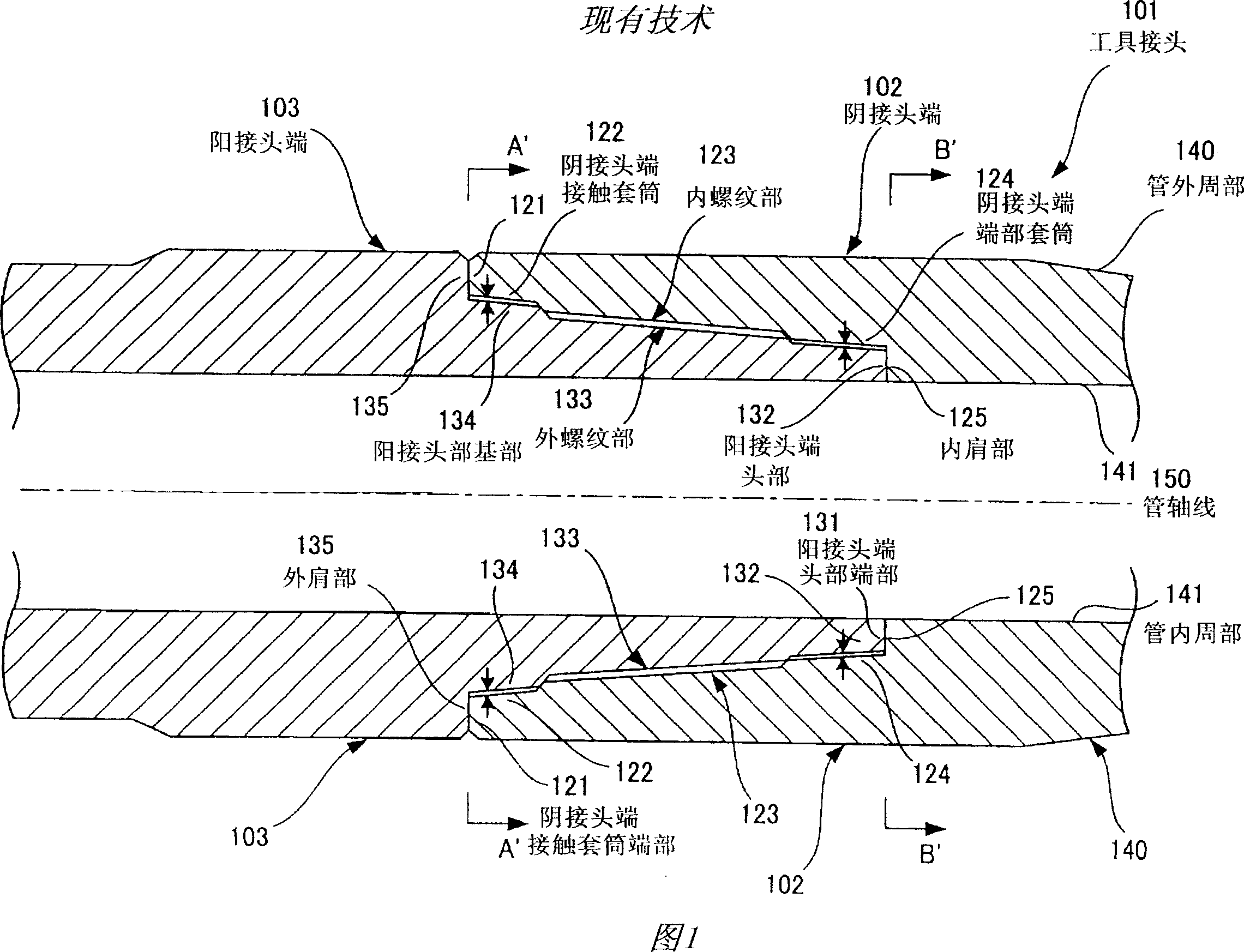
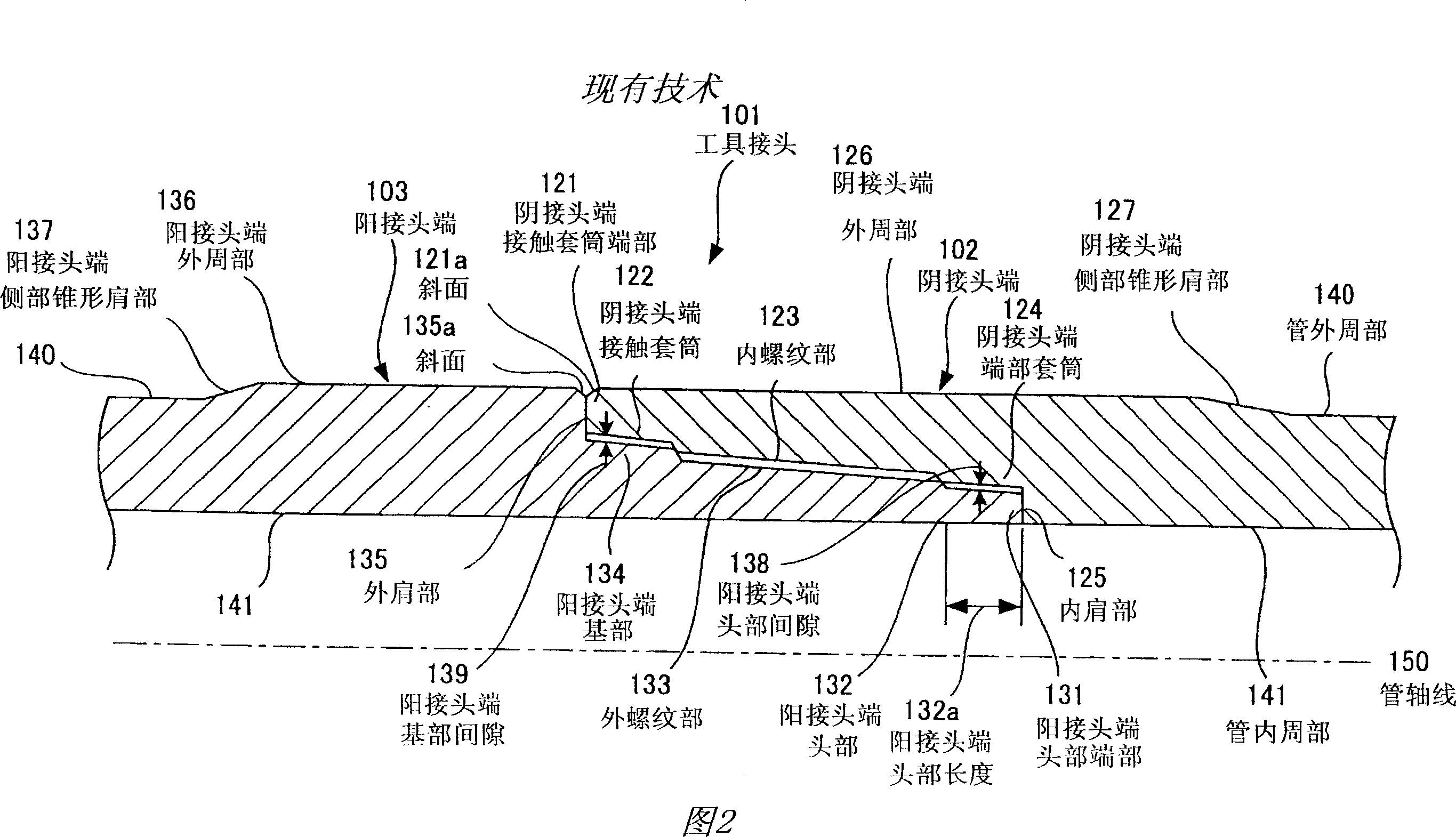
A tool joint and double-shoulder technology, applied in the field of double-shoulder tool joints, can solve problems such as thread damage, difficulty in meeting, and reduced drilling efficiency, and achieve the effect of improving operability and prolonging service life

Inactive Publication Date: 2007-03-21
NKKTUBES
View PDF1 Cites 3 Cited by
  • Summary
  • Abstract
  • Description
  • Claims
  • Application Information

AI Technical Summary

Problems solved by technology

[0004] However, when the pipe body is of a high strength grade, the conditions provided in this standard are often difficult to meet
Therefore, in conventional tool joints for drill pipes, the disadvantages are that the drilling efficiency is reduced due to the limitation of the drilling conditions, and the disadvantages are that the threads are damaged.

Method used


Image

  • Double shoulder tool joint
  • Double shoulder tool joint
  • Double shoulder tool joint

Examples


Embodiment 1

[0077] Embodiment 1 of the present invention will be explained below.

[0078] In Embodiment 1, the pin end and the box end are made of SAE 4137H-based material (structural steel material with a certain degree of hardenability) according to the AISI (American Iron and Steel Institute) standard. A representative composition of SAE 4137H based material is by weight: C 0.37%, Si 0.2%, Mn 1.0%, Cr 1.0%, and Mo 0.2%. The strength of the material is determined according to API Spec.7. Use male and female ends with an outside diameter of 177.8 mm and an inside diameter of 108.0 mm. The male and female ends are screwed together and clamped manually. This manual clamping angle is determined as the manual clamping position for reference. Next, when the pin end and box end are clamped with a predetermined torque by means of the clamping tool, the clamping angle and torque are plotted to obtain the torsional yield strength. At this time, the pin tip portion protrudes from the end port...

Embodiment 2

[0083] Embodiment 2 of the present invention will be explained below.

[0084] Example 2 was constructed the same as Example 1 except that the length of the pin head was 11 mm to obtain twist yield strength.

[0085] The test results are shown in FIG. 8 and Table 1. As can be understood from this result, the torsional yield of the tool joint in Example 2 starts at 101,700 N·m (clamping angle is 29°).


PUM

PropertyMeasurementUnit
Outer diameteraaaaaaaaaa
Diameteraaaaaaaaaa

Abstract

The tool joint 1 for drill pipe used for boring oil or gas well. The pin 3 is provided with an outside shoulder 35, a pin base 34 having an outer periphery surface parallel with the pipe axis 50, a male threaded part 33 having a predetermined taper to the pipe axis 50, and a pin nose 32 having an outer periphery surface parallel with the pipe axis 50. The box 2 is provided with a box access sleeve 22 having an inner periphery surface parallel with the pipe axis 50, a female threaded part 23 engaging by thread with the male threaded part 33, a box end sleeve 24 having an inner periphery surface corresponding to the outer periphery surface of the pin nose 32, and an inside shoulder 25. By increasing a total of a mating surface between the outside shoulder 35 and a box access sleeve end portion 21 and a mating surface between the inside shoulder 25 and a pin nose end portion 31, higher torque characteristics is realized without reducing the operativity.

Description

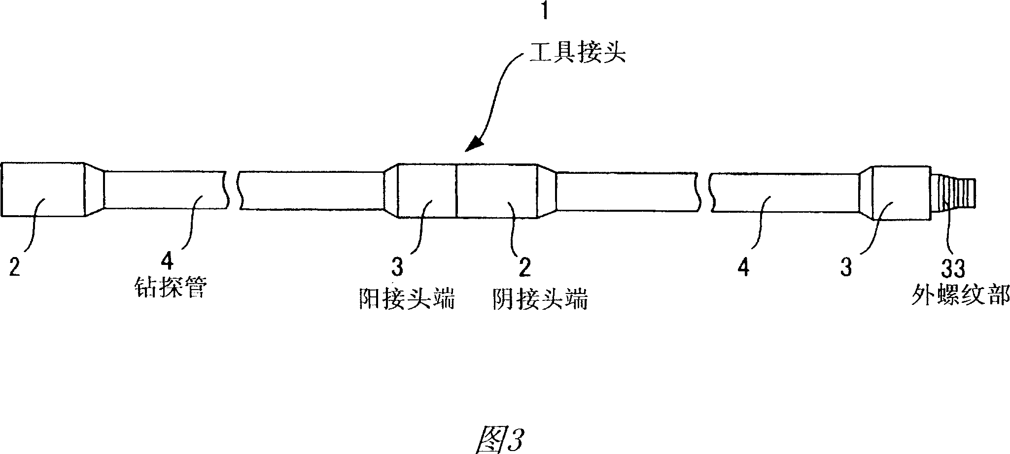
[0001] This application is based on Japanese Patent Application No. 2004-106970 filed on March 31, 2004, the entire content of which is incorporated herein by reference. technical field [0002] This invention relates to double shoulder tool joints for use on drill pipe for drilling oil or gas wells, and more particularly, to double shoulder tool joints for drill pipe which allow for higher torque characteristics without reduce operational efficiency. Background technique [0003] In the prior art, drill pipes for drilling extended-reach wells and horizontal wells are connected by means of tool joints. Details of tool joints are provided in the standard API (American Petroleum Institute) Spec.7. In this standard, the outer diameter of the tool joint is formed larger than the outer diameter of the pipe body, and the inner diameter of the tool joint is formed smaller than the inner diameter of the pipe body, thereby transmitting high torque required for drilling. In addition...

Claims


Application Information

Patent Timeline
IPC IPC(8): F16L15/04E21B17/042F16L15/06
CPCE21B17/042
Inventor 松岛顺佐仓弘持桑野岳志
Owner NKKTUBES
Learn More