
Motor vehicle hub driving device

A wheel drive, motor vehicle technology, applied in control devices, vehicle components, transportation and packaging, etc., can solve the problems of riders falling backwards, accidents, unsafe factors, etc., and achieve the effect of soft braking and convenient operation

Inactive Publication Date: 2007-03-28
广州天马集团天马摩托车有限公司
View PDF1 Cites 1 Cited by
  • Summary
  • Abstract
  • Description
  • Claims
  • Application Information

AI Technical Summary

Problems solved by technology

The driving device disclosed in Chinese Utility Model Patent Specification 98202373.1 "Overrunning Sliding Device" includes an overrunning clutch and a control clutch. The disadvantage is that this kind of driving device is a hard connection. When driving, the engine brake will be reversed immediately due to the hard connection of the operating clutch, resulting in unsafe factors, causing the rider to fall backwards or even fall immediately, resulting in an accident

Method used


Image

  • Motor vehicle hub driving device
  • Motor vehicle hub driving device
  • Motor vehicle hub driving device

Examples


Embodiment Construction

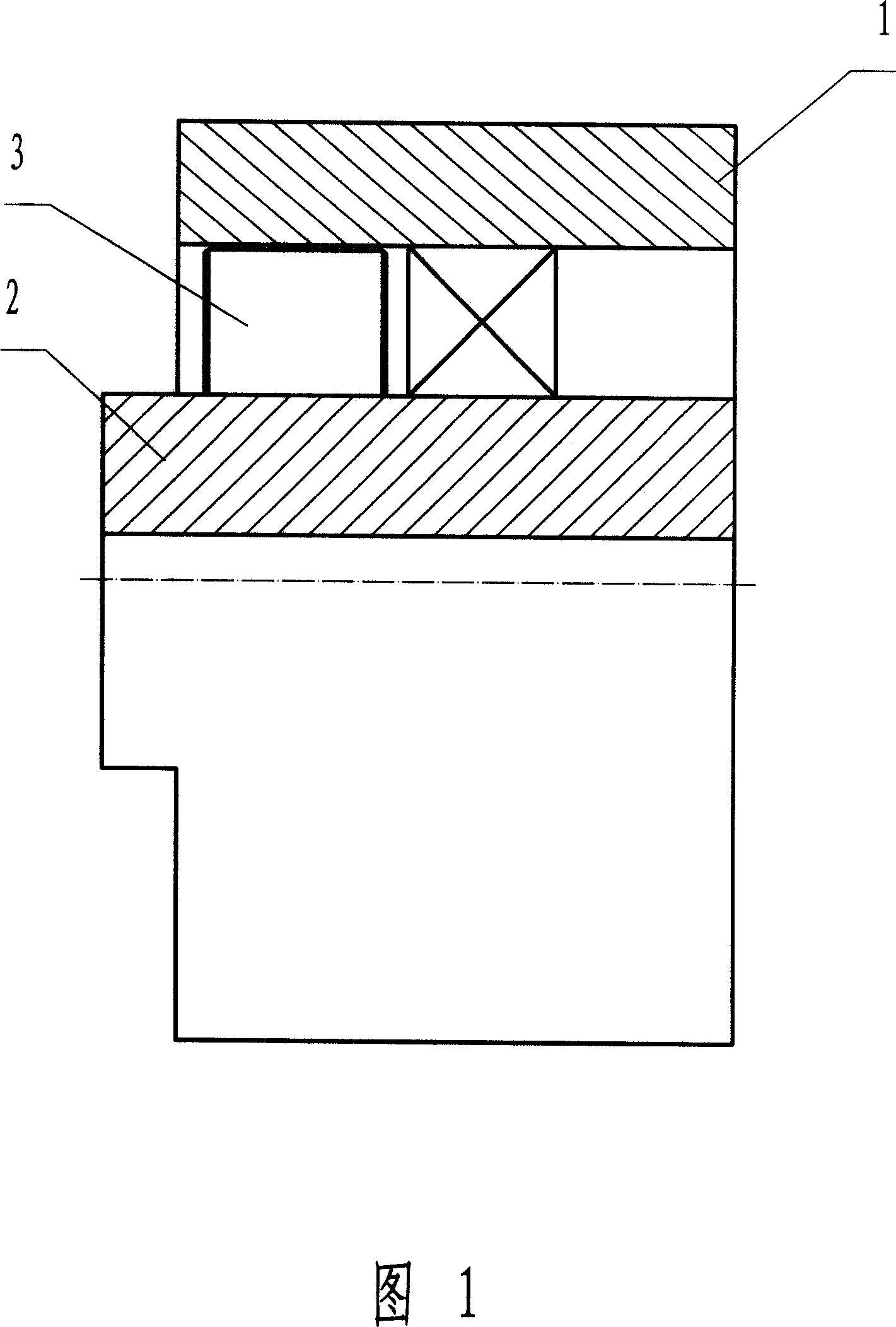
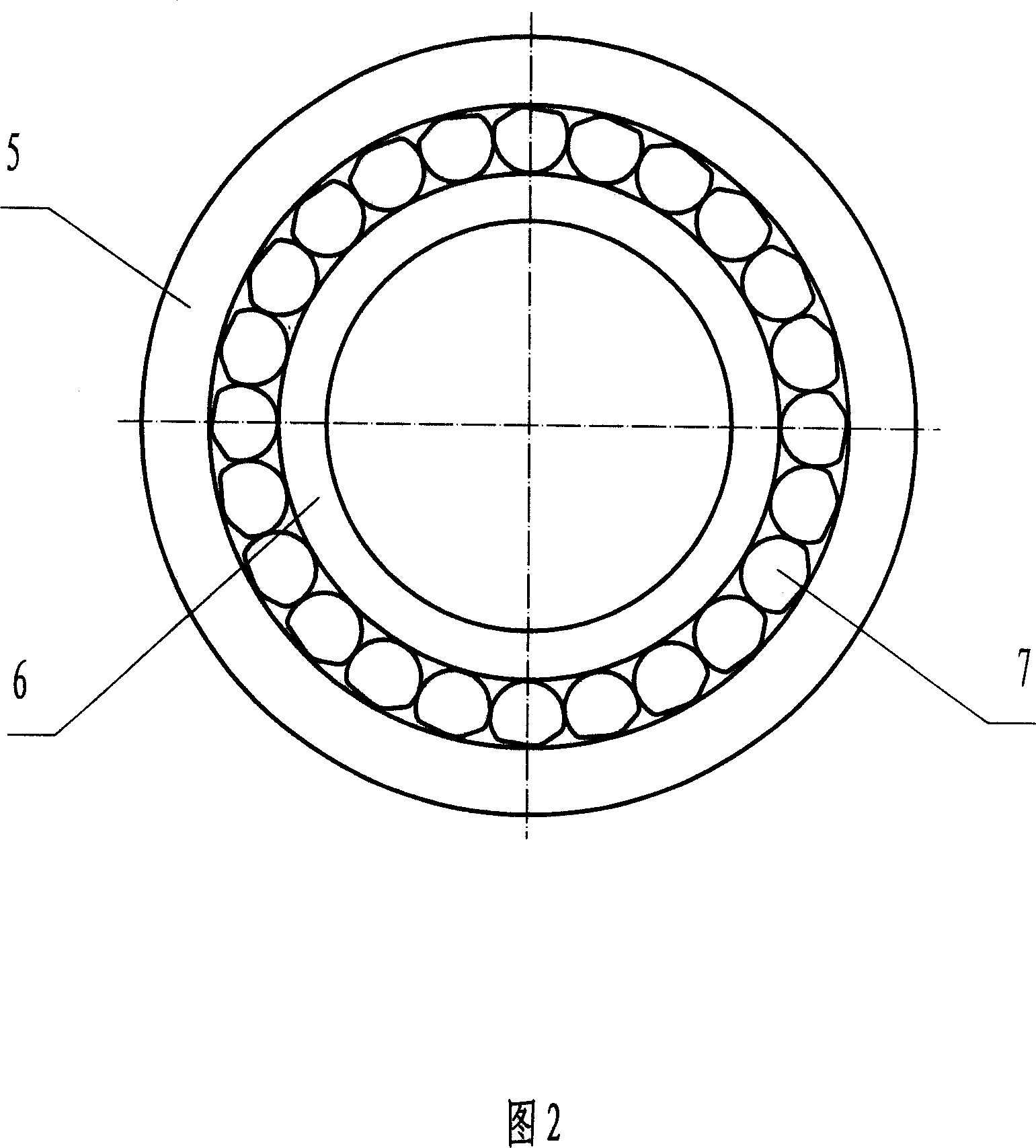
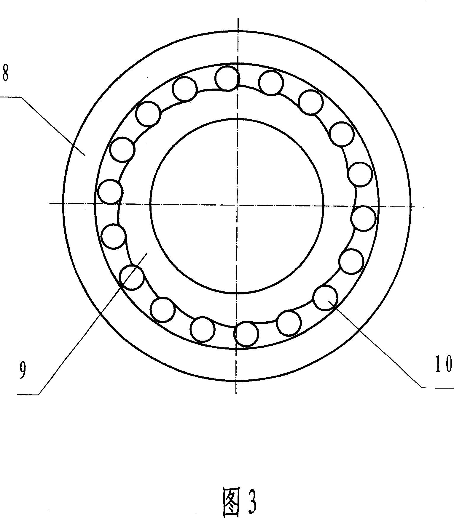
[0016] A specific embodiment is described as follows in conjunction with Fig. 3, Fig. 5 and Fig. 7: a motor wheel hub drive device with self-control clutch and control clutch, including wheel hub 1, drive shaft 2, self-control clutch 3 and control clutch 4, self-control clutch 3 adopts roller Column type overrunning clutch, the star wheel 9 is installed on the drive shaft 2, and the roller 10 is located in the wedge-shaped gap on the star wheel 9 between the wheel hub 1 and the star wheel 9. The steering clutch 4 adopts a friction plate type mechanical clutch, its output shaft 22 is connected with the drive shaft 2, the friction plate seat 23 is installed on the right section of the drive shaft 2, and the internal tooth friction plate 24 is mounted on the outer surface of the friction plate seat 23 with its internal teeth In the spline groove of the outer tooth friction plate 25, its outer teeth are installed in the spline groove of the right section of the inner wall of the hu...


PUM


Abstract

The invention is an engine hub driver, belonging to the technical field of hub drivers, providing a flexible connected driver, compriisng hub, drive shaft, auto-controlled clutch and controlled clutch, where the drive shaft is arranged in the hub, the auto-controlled clutch is arranged between the left segments of the hub and drive shaft, and the controlled clutch is arranged between their right segments; a spider of the auto-controlled clutch is arranged on the drive shaft, the roller is arranged between the spider and the hub, when the speed of the spider is higher than that of the hub, the drive shaft drives the hub through the spider, and when the speed of the hub is higher than that of the spider, the hub exceeds the drive shaft to rotate; the input end of the controlled clutch is connected with the hub and the output end of the controlled clutch is connected with the drive shaft, and ordinarily, the controlled clutch is separated from the hub and the drive shaft but jointed with them by control so that the hub can be driven by the drive shaft to reversely drag the engine.

Description

technical field [0001] The utility model belongs to the technical field of motor wheel hub driving devices. Background technique [0002] The prior motor wheel hub driving device generally includes a wheel hub and a drive shaft, and the drive shaft directly drives the wheel hub with simple functions. The driving device disclosed in Chinese Utility Model Patent Specification 98202373.1 "Overrunning Sliding Device" includes an overrunning clutch and a control clutch. The disadvantage is that this kind of driving device is a hard connection. When driving, the engine brake will be reversed immediately due to the hard connection of the operating clutch, resulting in unsafe factors, causing the rider to fall backwards or even fall immediately, resulting in an accident. Contents of the invention [0003] The technical problem to be solved is to provide a motor wheel hub drive device with flexible connection. [0004] The technical solution to solve its technical problems is as ...

Claims


Application Information

Patent Timeline
Patent Type & Authority Applications(China)
IPC IPC(8): B60K17/02
Inventor 刘建平
Owner 广州天马集团天马摩托车有限公司
Learn More