Device for adjusting fixed position of detector

A fixed position and detector technology, applied in the field of radiation detection, can solve the problems of no fine adjustment, inconvenient installation and debugging of detectors, and inconvenient maintenance in the later stage, and achieve the effect of fine adjustment of spatial position and precise positioning

Inactive Publication Date: 2007-03-28
NUCTECH CO LTD +1
View PDF0 Cites 4 Cited by
  • Summary
  • Abstract
  • Description
  • Claims
  • Application Information

AI Technical Summary

Problems solved by technology

However, the existing detector fixing device has no fine adjustment function, so that

Method used


Image

  • Device for adjusting fixed position of detector

Examples


Embodiment Construction

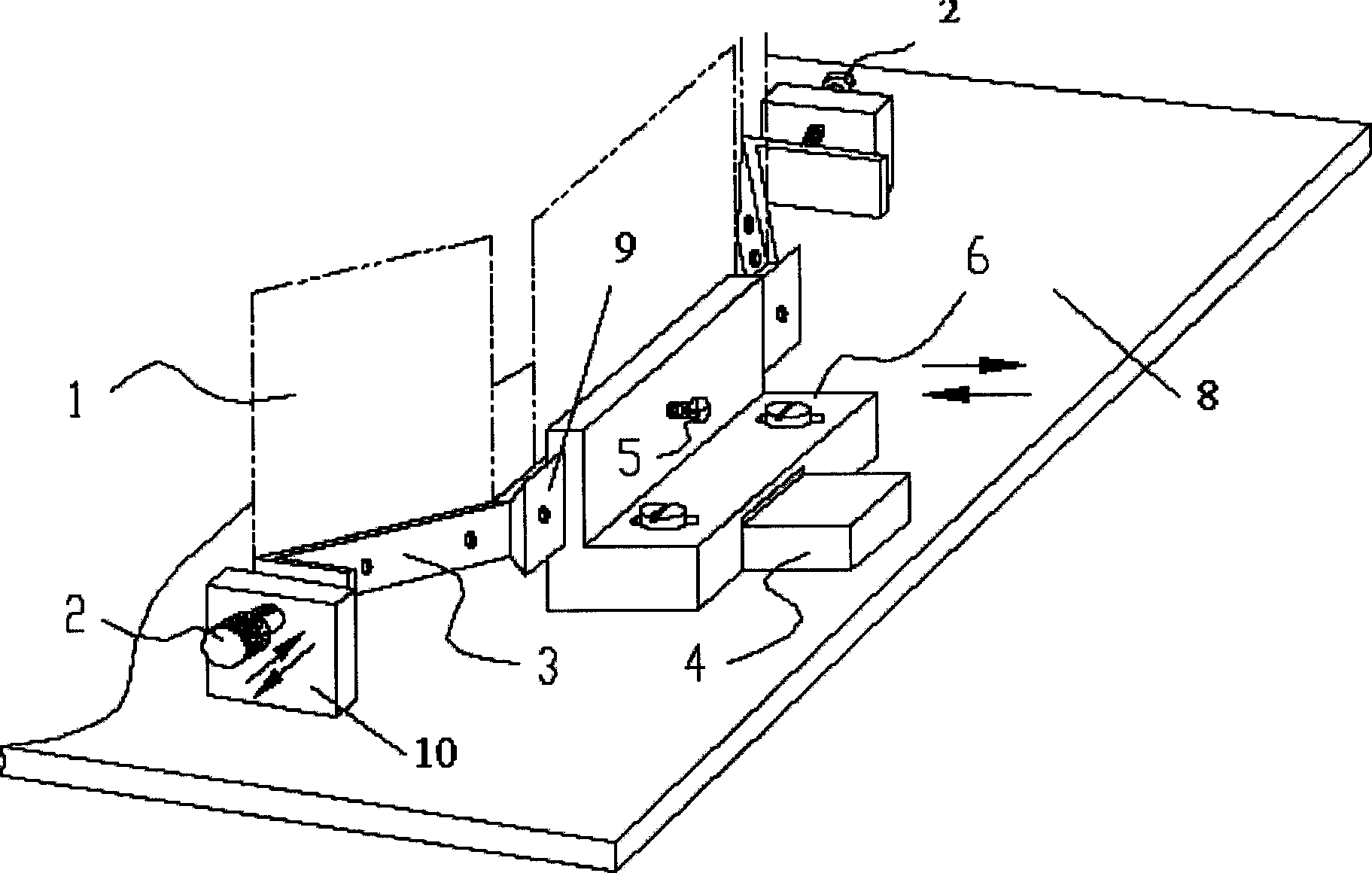
[0012] The embodiments of the present invention will be further described below in conjunction with the accompanying drawings.

[0013] Referring to the accompanying drawings, the present invention includes a base 6 that can be fixed on a base plate 8 and has a lateral slide groove 9 , and a carriage 3 that can be embedded in the horizontal slide groove 9 and that can install a detector module 1 . The lateral displacement of the slide frame 3 is adjusted by the micrometer head 2 on the frame plate 10 fixed on the base plate 8 . The base 6 is provided with screws 5 for positioning and fixing the carriage 3 . The horizontal slide groove 9 is a dovetail groove. The line profile of the carriage 3 is a broken line. The base 6 is L-shaped, and the rear portion of the base 6 is provided with a positioning block 4 . The micrometer head 10 is a dividing head rod structure or a bolt. Micrometer heads 10 are arranged on both sides of the carriage 3 .

[0014] Of course, according to...


PUM


Abstract

This invention discloses a device for adjusting the fixed positions of detectors used in the device for carrying out CT safety check to liquid articles by radial sources including a base seat with a lateral sliding groove fixed on the base plate and a sliding frame inserted in the lateral sliding groove and mounted with detector module, in which, the lateral displacement of the frame is adjusted by a micrometer head of a frame plate fixed on the base plate and bolts are set on the base seat for locating and fixing the sliding frame.

Description

technical field [0001] The invention belongs to the technical field of radiation detection. The invention relates to a radiation liquid safety inspection system, in particular to a device for adjusting the fixed position of a detector used in radiation liquid safety inspection system equipment. Background technique [0002] In the prior art, due to the small size of the radiation liquid safety inspection system equipment, the detectors are arranged in a fan shape, and the corresponding position of the detectors to the beam exit of the rear collimator is required to be accurate. However, the existing detector fixing device has no fine adjustment function, so that it is very inconvenient to install, debug and maintain the detector. Contents of the invention [0003] In order to solve the deficiencies in the prior art, the object of the present invention is to provide a device for adjusting the fixed position of the detector, which has a compact structure and can finely adju...

Claims


Application Information

Patent Timeline
IPC IPC(8): G01N23/00G01D11/02G12B3/00
Inventor 李元景刘以农陈志强吴万龙李玉兰罗希雷张丽赵自然桑斌王海林
Owner NUCTECH CO LTD
Why Eureka
Try Eureka