
Selection actuator for knitting member

A technology of woven parts and actuators, which is applied in weft knitting, knitting, textiles and papermaking, etc., which can solve the problems such as difficult to reliably select woven parts, and achieve the effects of small changes in magnetic impedance and uniform magnetization

Inactive Publication Date: 2007-03-28
SHIMA SEIKI MFG LTD
View PDF3 Cites 7 Cited by
  • Summary
  • Abstract
  • Description
  • Claims
  • Application Information

AI Technical Summary

Problems solved by technology

This makes it difficult to reliably select knitted components

Method used


Image

  • Selection actuator for knitting member
  • Selection actuator for knitting member
  • Selection actuator for knitting member

Examples


Embodiment

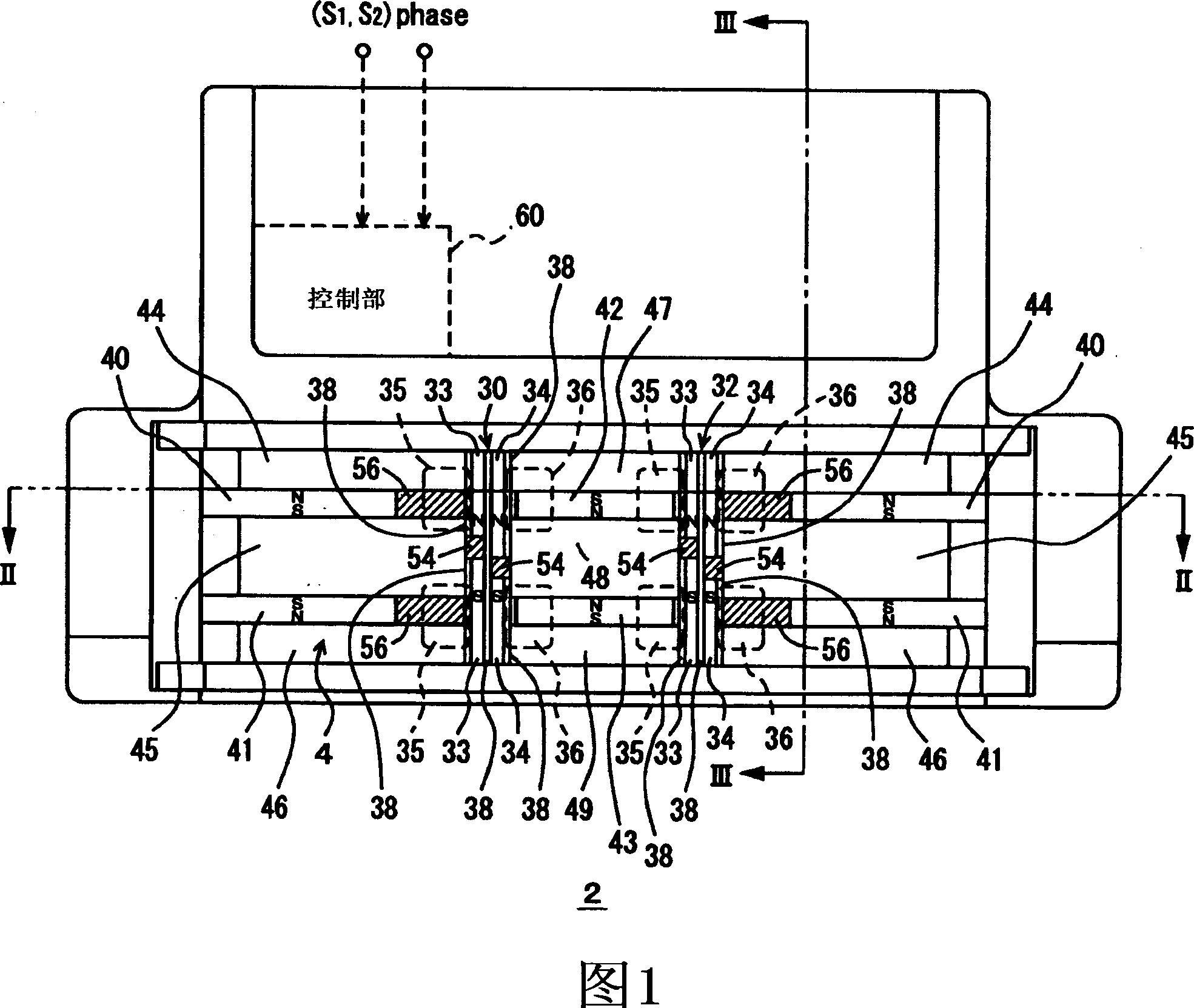
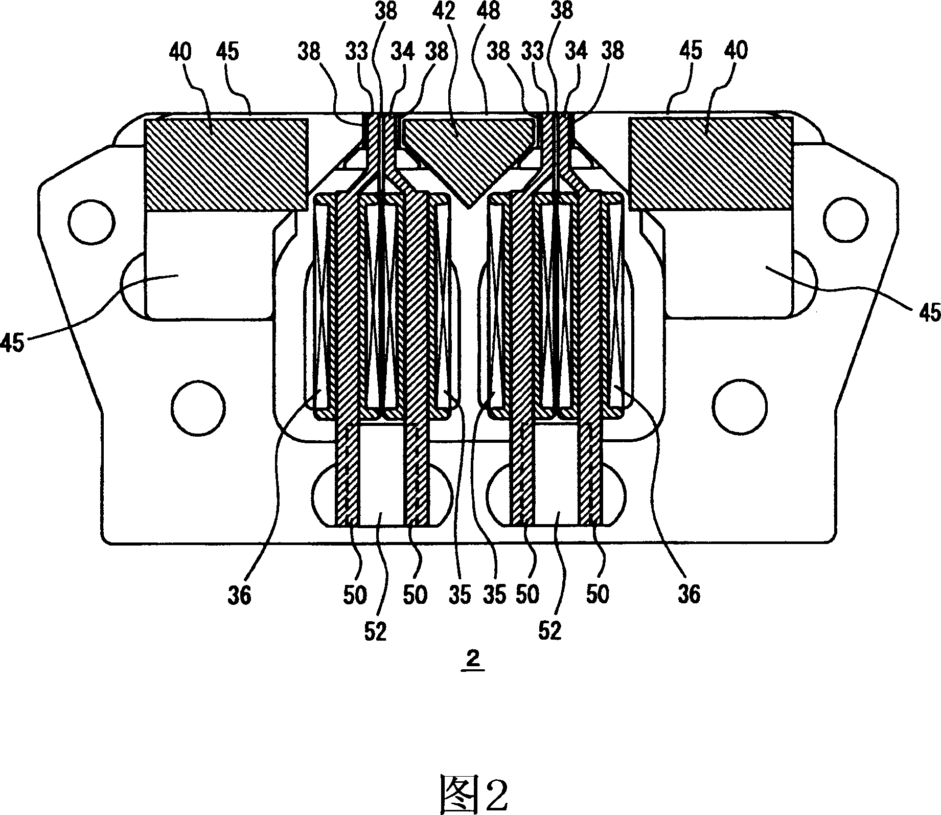
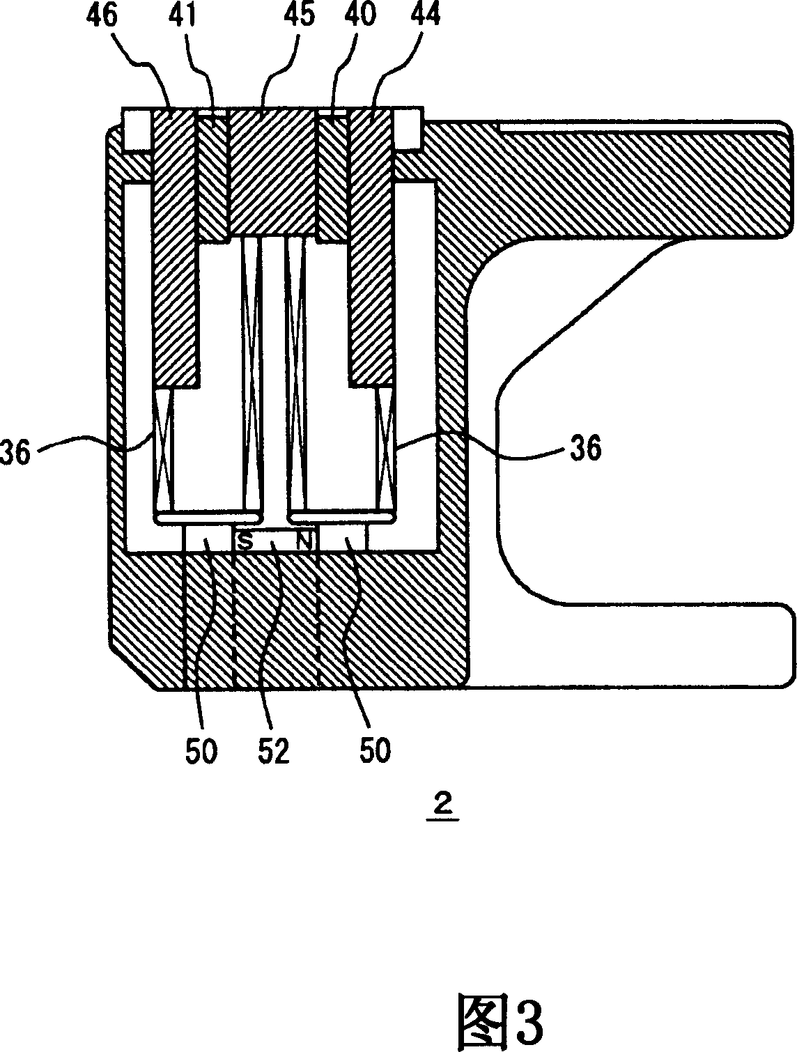
[0077] 1 to 11 show the selective actuator 2 of the embodiment and its modification. The selection actuator 2 has an acting part 4 on the upper surface, and selects the selector jack of the knitting needle of the flat knitting machine, and selects the knitting needle to which the cam of the carriage carriage acts and the knitting needle that is not to act. The relationship between the knitting needle 6 and the selection actuator 2 is shown in FIG. 8. 7 is the foot piece, 8 is the needle selection foot piece, 10 is the needle selection piece, they are part of the knitting needle 6. 12 is a butt provided on the selector jack 10. The selector jack 10 is forced upward in FIG. 8 by the elastic foot 14, and the armature 16 of the selector jack 10 is selected by the selection actuator 2. The knitting needles 6 are housed in the needle bed 18, the carriage 20 moves relative to the needle bed 18, and the selection actuator 2 is installed on the carriage 20. 21 and 22 are metal belts set on...


PUM


Abstract

A plurality of control magnetic poles 33n-34n are provided in each selection unit of a selection actuator, and the upstream control magnetic poles 33n, s and downstream control magnetic poles 34n, s are controlled independently based on the relative positions thereof to selectors. The selectors can be selected with a pitch approximately half the pitch at which selection is possible with the conventional selection actuator and the time used for selecting each selector can be extended. Therefore, a knitting member can be reliably selected even in a fine-gauge knitting machine.

Description

Technical field [0001] The present invention relates to an actuator for selecting knitted components such as knitting needles and transfer components in flat knitting machines, circular knitting machines, and the like. Background technique [0002] In flat knitting machines, circular knitting machines, etc., knitting parts such as knitting needles are selected by a selection actuator, and the selected knitting needles are driven by a cam of a carriage. As a problem of selecting an actuator, there is a problem corresponding to a knitting machine with a high gauge (fine pitch). The gauge of a knitting machine indicates the number of needles within 1 inch. For high gauges, it is necessary to select knitted parts with small pitches. [0003] Patent Document 1 discloses a technique of inserting a non-magnetic magnet between the control magnetic pole (the state of magnetization is controlled by a coil and the magnetic pole of the braided component is selected) and the fixed magnetic po...

Claims


Application Information

Patent Timeline
Patent Type & Authority Applications(China)
IPC IPC(8): D04B15/82D04B15/78
CPCD04B15/78D04B15/82D04B15/66
Inventor 上山裕之
Owner SHIMA SEIKI MFG LTD
Learn More