Panel structure and kitchen base with the same

A structure and core board technology, applied in kitchen cabinets, building structures, cabinets, etc., can solve problems such as troublesome replacement of decorative boards

Inactive Publication Date: 2007-03-28
SUN WAVE CO LTD
View PDF2 Cites 7 Cited by
  • Summary
  • Abstract
  • Description
  • Claims
  • Application Information

AI Technical Summary

Problems solved by technology

[0004] However, in Patent Document 1, when replacing the decorative board (surface board), the decorative board must be removed from the fram

Method used


Image

  • Panel structure and kitchen base with the same
  • Panel structure and kitchen base with the same
  • Panel structure and kitchen base with the same

Examples


Embodiment 1

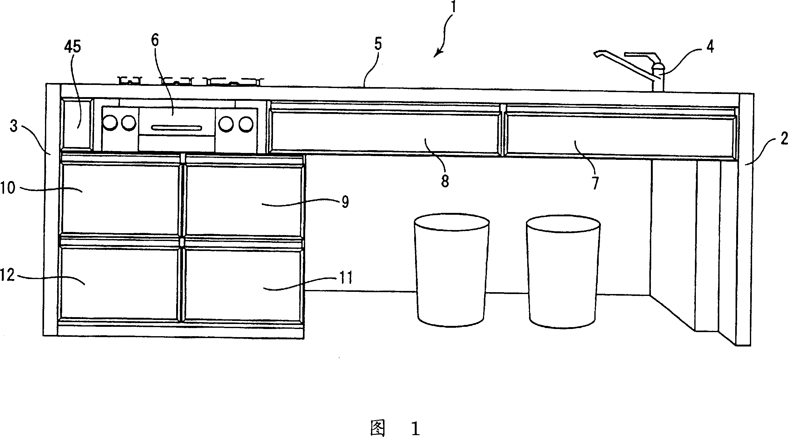
[0032] Embodiments of the present invention will be described below with reference to the drawings. First, FIG. 1 is a front view showing the overall appearance of a kitchen cabinet according to Embodiment 1 of the present invention. The reference numeral 1 in Fig. 1 is a kitchen cabinet constructed with the panel of the present invention. The kitchen cabinet 1 is provided with legs 2, 3 on the left and right, and a top 5 provided with a faucet 4, a water tank (not shown), etc. is arranged on the top of the legs 2, 3. On the lower part of the table top 5, a gas burner 6 and drawers 7 and 8 that can be drawn out to the front side are arranged side by side. In addition, below the gas stove 6, there are also four drawers 9, 10, 11, 12 that can be pulled out to the front.

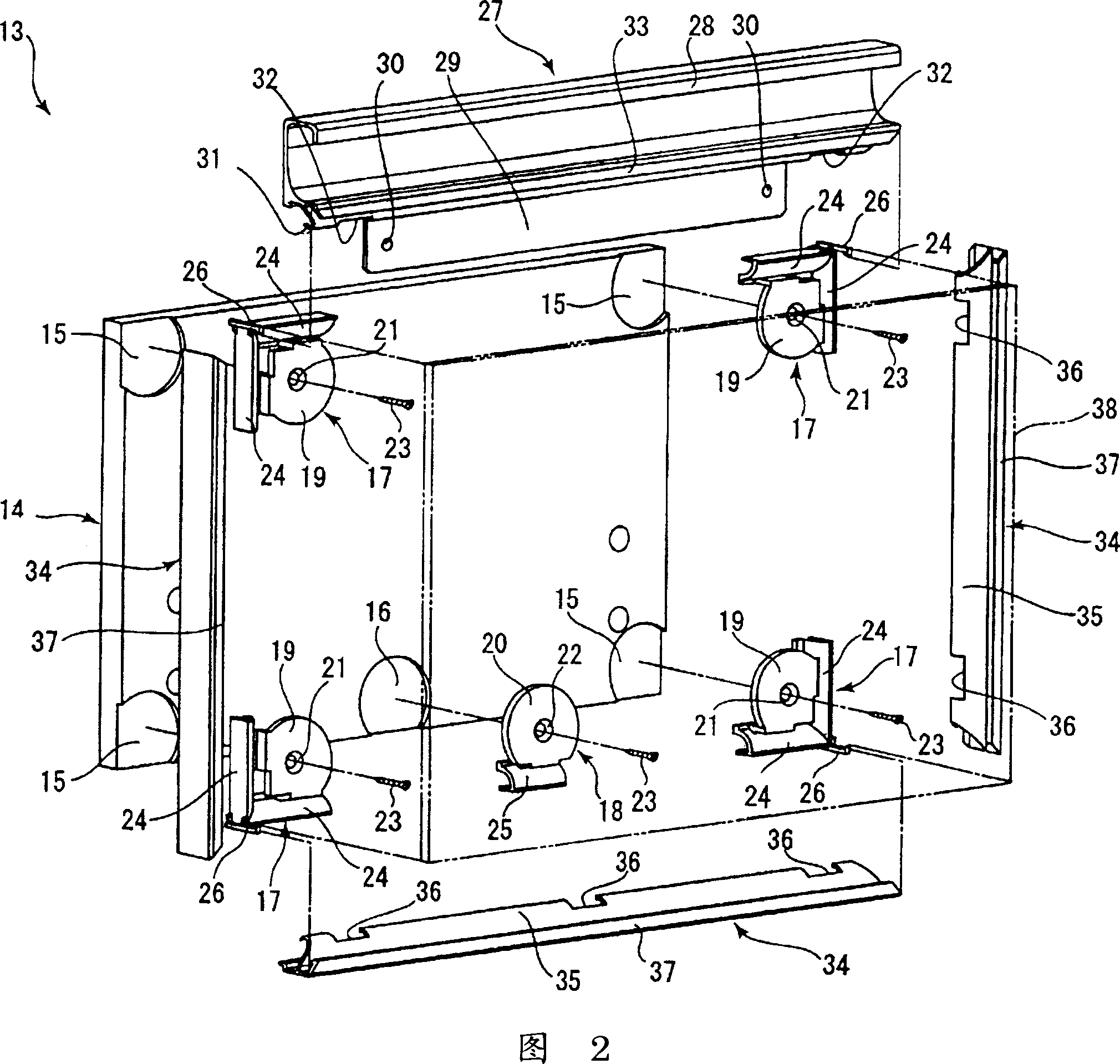
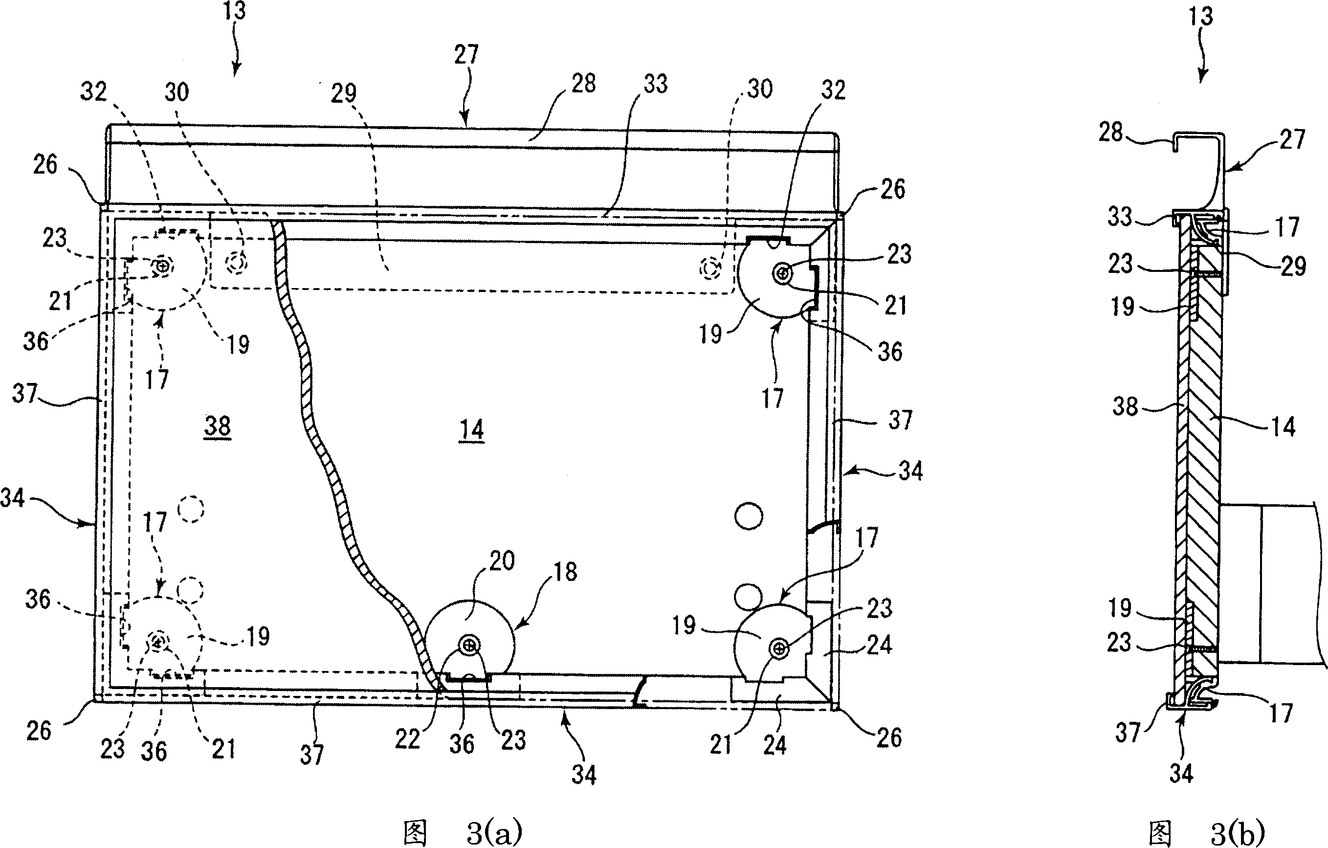
[0033] These four drawers 9, 10, 11, and 12 have the same structure, so only the drawer 9 will be described as an example. On the front side of the drawer 9, a front panel 13 having a panel structure accordi...

Embodiment 2

[0063] Next, the plate structure of Example 2 will be described with reference to FIG. 5 . Description of the same configuration as the above-mentioned embodiment is omitted.

[0064] Fig. 5 is an exploded perspective view showing the front panel 46 of the drawer according to the second embodiment of the present invention. The front panel 46 has a middle board 47 as a core board in this embodiment, and a decorative board 48 as a surface board in this embodiment is attached to the front side of the middle board 47 . Two recesses 49 are formed on the lower portion of the middle plate 47 , and a handle frame 50 is attached to the upper side of the middle plate 47 . A horizontally long handle 51 extending in the longitudinal direction is provided on the upper portion of the handle frame 50 .

[0065] As shown in Figure 5, a rectangular mounting fitting 52 extending downwards and installed on the rear side of the middle plate 47 is provided at the rear of the handle frame 50, and...


PUM


Abstract

A panel structure in which a surface panel can be easily removed from frame members and which is solid. Frame members (17, 18, 34) having at least engagement pieces (24, 25), a hook (35) engageable with the engagement pieces (24, 25), and pressing pieces (37) foldable together with the hook (35) are provided at at least one side of a core panel (14), and a surface panel (38) can be removably held between the core panel (14) and the press-down piece (37).

Description

technical field [0001] The present invention relates to panel construction for front panels of doors or drawers or the like. Background technique [0002] In the past, the panel structure used for the front panel of a door or a drawer has such a structure that a frame strip formed in a U-shaped cross section is arranged on the peripheral edge of a flat decorative panel, and the frame strip is embedded in the peripheral edge of the decorative panel, and screwed, etc. The frame bars are fixed to each other (for example, refer to Patent Document 1). [0003] Patent Document 1: Japanese Patent Laid-Open No. 2001-159275 (page 2, FIG. 2 ) [0004] However, in Patent Document 1, when the decorative panel (surface panel) is replaced, it is necessary to remove the decorative panel from the frame after removing the screws for fixing the frame bars to each other. Therefore, the replacement of the decorative panel is very troublesome. Contents of the invention [0005] This inventio...

Claims


Application Information

Patent Timeline
IPC IPC(8): E06B3/72A47B77/00A47B88/00A47B96/20A47G1/06A47B77/02E06B5/00F16B12/20
CPCE06B5/006F16B12/2009A47B96/206A47B77/022A47B96/201
Inventor 吉田洋行高久秀之
Owner SUN WAVE CO LTD
Why Eureka
Try Eureka