
Roll harnessing equipment and rolling method

A jig and rounding technology, applied in the direction of manufacturing tools, clamping, support, etc., can solve the problems of uneven distribution of UV glue, loose dislocation, inconsistent rounding conditions, etc.

Inactive Publication Date: 2007-04-04
HONG FU JIN PRECISION IND (SHENZHEN) CO LTD +1
View PDF0 Cites 3 Cited by
  • Summary
  • Abstract
  • Description
  • Claims
  • Application Information

AI Technical Summary

Problems solved by technology

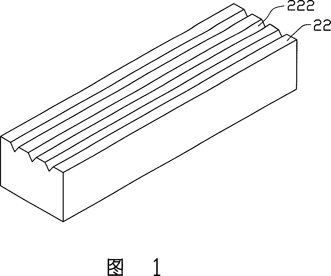
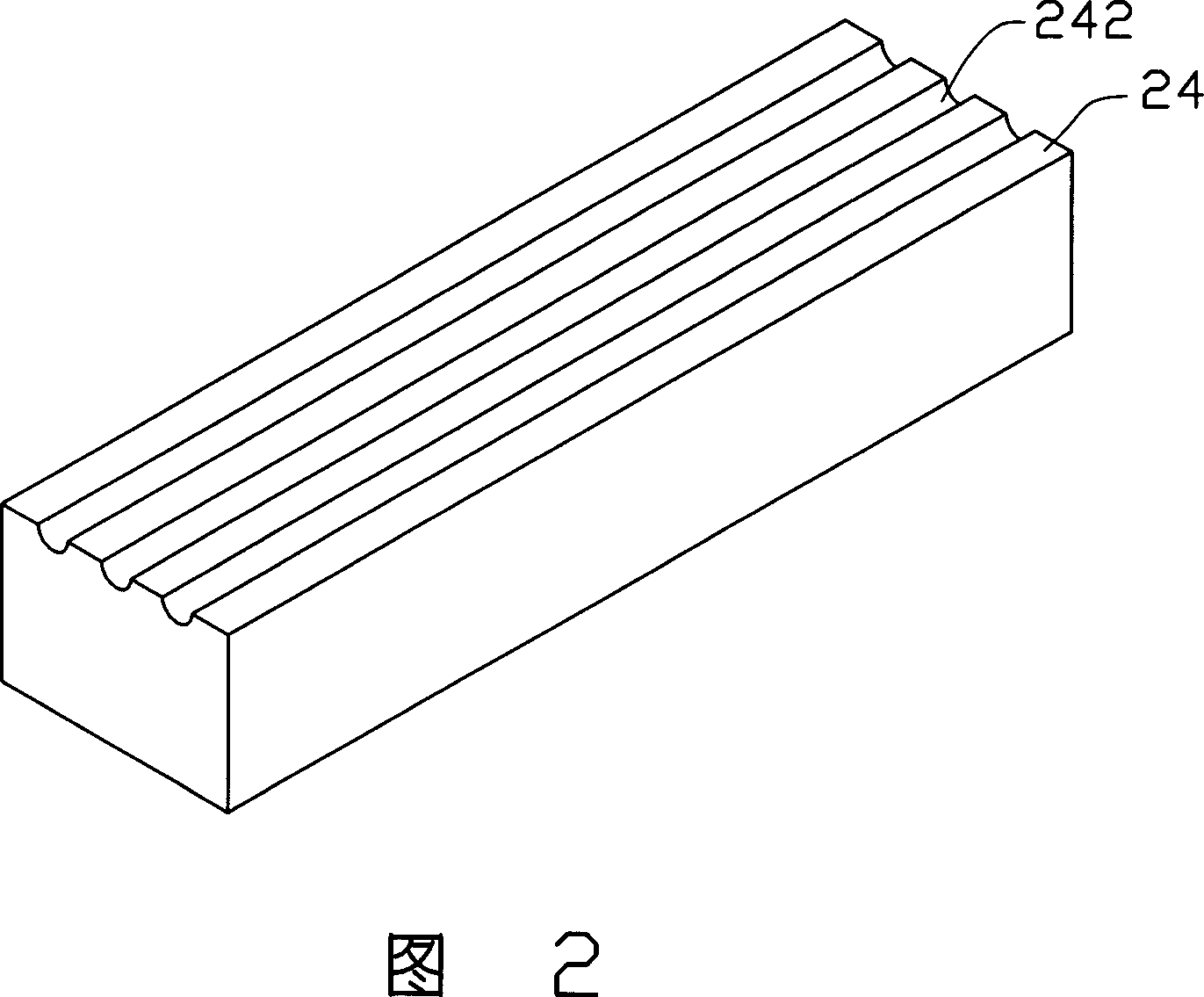
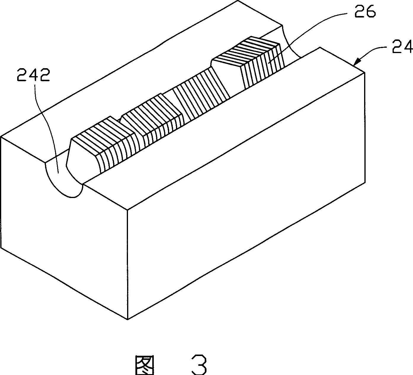
[0004] However, in the above method, in order to make the workpiece 26 be ground by the first jig 22 and move to the second jig 24, it must be soaked in water or other solutions to separate the workpiece 26 from the first jig 22, and then Only then can the workpiece 26 be transferred to the second fixture 24. During the transfer process of the workpiece 26, the UV glue will decompose and cause loosening and dislocation, as shown in Figure 3; in addition, because the workpiece 26 is transferred to the second fixture 24 Finally, unevenly distributed UV glue remains on the non-rounded surface of the workpiece 26. At this time, the first jig 22 cannot be pressed down to achieve the effect of automatic correction, thus causing inconsistent grinding conditions of each workpiece 26, which affects the processing quality. Rate

Method used


Image

  • Roll harnessing equipment and rolling method
  • Roll harnessing equipment and rolling method
  • Roll harnessing equipment and rolling method

Examples


Embodiment Construction

[0024] Referring to FIG. 4 and FIG. 5 , a preferred embodiment of the rounding jig of the present invention includes a first jig 42 and a second jig 44 . Please refer to FIG. 6 , the rounding jig is used for rounding the lens 46 of the camera lens.

[0025] The first jig 42 is in the shape of a cuboid and includes a first surface 420. A groove 422 is provided on the first surface 420. A plurality of parallel grooves 422 can also be provided on the first surface 420, thereby Multiple groups of lenses 46 can be rounded at the same time. This embodiment is described by taking a groove 422 as an example. The cross-sectional shape of the groove 422 is funnel-shaped, that is, a part of the groove 422 is a square groove, and a part is a trapezoidal groove. 424 , the angle between the two slopes 424 and the first surface 420 of the first jig 42 is 45°.

[0026] The second jig 44 is in the shape of a cuboid, and includes a second surface 440, on which a semicircular groove 442 is pro...


PUM


Abstract

A die set for grinding circular lens is composed of the first die with a slot on its top surface, and the second die with semi-circular slot. Its method for grinding circular lens includes such steps as providing said die se, fixing the lens in the slot of the first die, grinding the exposed part of the lens to become semi-circular shape, putting the second die on the first one to make the semi-circular part of the lens in the semi-circular slot of the second die, removing the first die, fixing the lens, grinding the exposed part of the lens to become a circular lens and separating the lens from the second die.

Description

【Technical field】 [0001] The invention relates to a rounding jig and a rounding method, in particular to a rounding jig and a rounding method for rounding lenses. 【Background technique】 [0002] Cylindrical grinder is a machine used to process workpieces of various shapes into a circle. Its working principle is to use a high-speed rotating grinding wheel to grind the workpiece fixed by the grinding machine fixture to process it into the required circle. shape. The general grinding machine fixing device is a pair of hollow fixtures. Firstly, the workpiece is adsorbed on one of the fixtures by using the suction pump to suck air into the hollow part of the fixture, and then the other fixture is approached to clamp and fix the workpiece, and then the grinding wheel is used for grinding. . This fixture can be widely used in the rounding or rounding process of workpieces with general shapes. However, it can only fix one workpiece at a time, so it can only grind one workpiece at ...

Claims


Application Information

Patent Timeline
Patent Type & Authority Applications(China)
IPC IPC(8): B23Q3/06B24B5/22B24B5/307
Inventor 颜士杰
Owner HONG FU JIN PRECISION IND (SHENZHEN) CO LTD
Learn More