Non-volatile memory circuit and its setting method

A non-volatile, memory technology, applied in the direction of circuits, electrical components, electrical solid-state devices, etc., can solve problems such as differences in physical structures

Active Publication Date: 2007-04-04
MACRONIX INT CO LTD
View PDF0 Cites 0 Cited by
  • Summary
  • Abstract
  • Description
  • Claims
  • Application Information

AI Technical Summary

Problems solved by technology

[0007] The purpose of the present invention is to provide a non-volatile memory circuit. The non-volatile memory uses continuous charging to inject and store charge to the memory element for setting, so as to solve the problem of the memory element being affected by the manufacturing process. The resulting differences in physical structure, and thus the resulting problems

Method used


Image

  • Non-volatile memory circuit and its setting method
  • Non-volatile memory circuit and its setting method
  • Non-volatile memory circuit and its setting method

Examples


Embodiment Construction

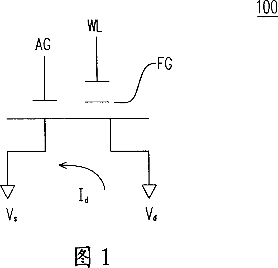
[0064] The biggest feature of the non-volatile memory circuit and its setting method proposed by the present invention is to use continuous charging to inject charges into the memory elements in the memory, so that it can be determined that each group of memory elements can be injected Sufficient charge count for correct setting action.

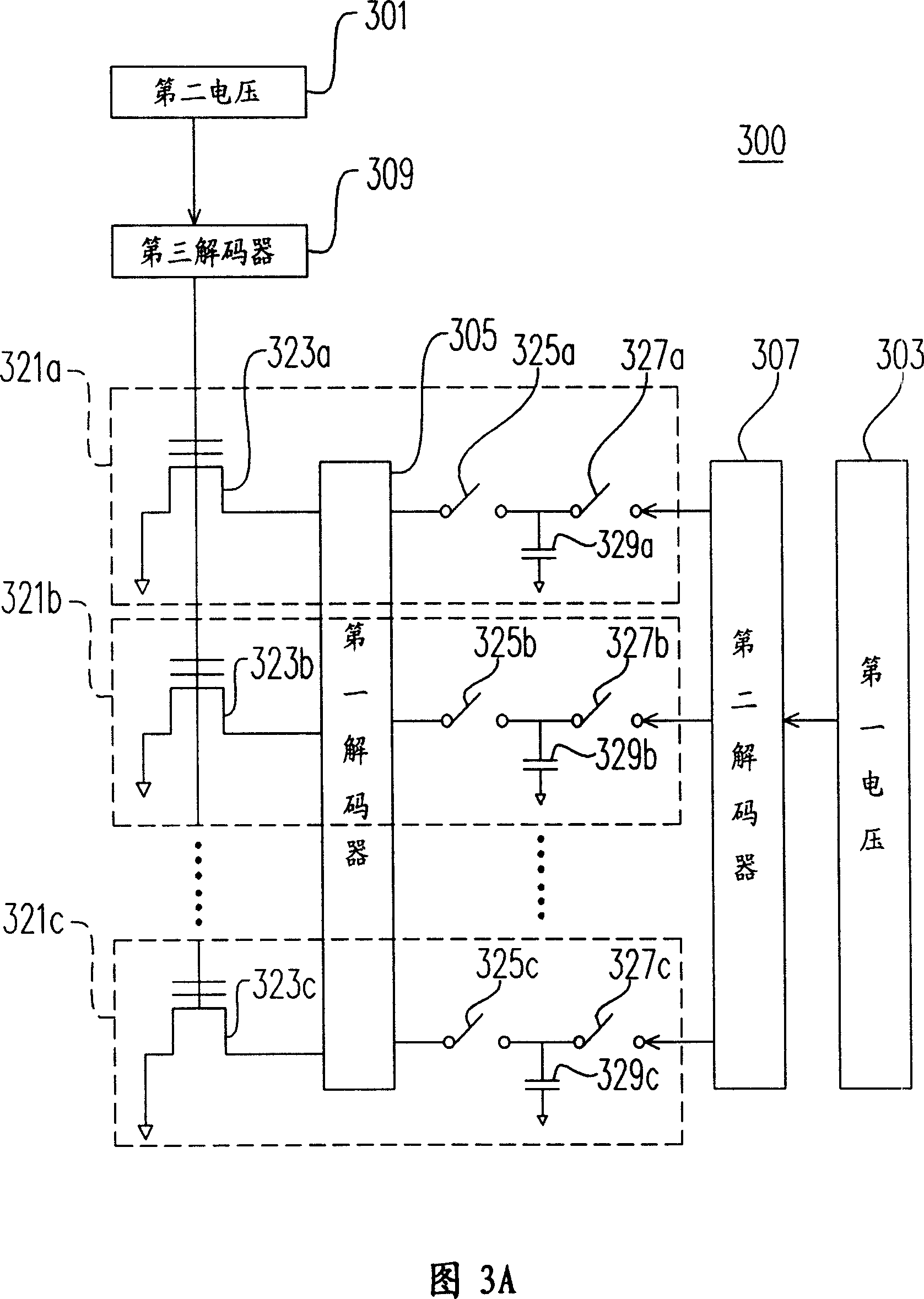
[0065] Please refer to FIG. 3A , which shows a structure diagram of an internal circuit of a non-volatile memory according to the present invention. As shown in the figure, the non-volatile memory 300 includes three sets of memory units 321a-321c. Of course, for those skilled in the art, the non-volatile memory 300 may include more sets of memory units.

[0066] In addition, the above-mentioned non-volatile memory circuit also includes two sets of voltage sources of the second voltage 301 and the first voltage 303 . Wherein, each group of memory units 321 mentioned above includes a second switch 325 , a first switch 327 , a voltage storage e...


PUM


Abstract

A non-volatility memory circuit is composed by several memory units, each of them includes the first switch, the second switch, data line and several splice memory parts. The first end of the first switch is connected to the first voltage; the second end is connected to data line. The first end of the second switch is connected to the data line. The third end of each memory parts is connected to the first end of the next; the second end of each memory parts is connected to the second voltage.

Description

technical field [0001] The present invention relates to a non-volatile memory, and in particular to a non-volatile memory circuit and its setting method using a continuous charging mode to set the storage state. Background technique [0002] Please refer to FIG. 1 , which is a schematic diagram of a conventional AG-AND type memory. This AG-AND memory 100 uses the current Id to flow from the Vd terminal to the Vs terminal, and injects and stores electrons in the memory. 100 in the Floating Gate (FG) terminal to complete the storage setting action of the memory. The biggest difference between this AG-AND memory 100 and general transistors is that its gate terminal contains two control terminals, which are WL terminal and AG terminal respectively. Therefore, when the AG-AND memory 100 needs to conduct the current Id When flowing from the Vd terminal to the Vs terminal, the two terminal voltages of the WL terminal and the AG terminal must be controlled at the same time to carry...

Claims


Application Information

Patent Timeline
IPC IPC(8): G11C16/02H01L27/115
Inventor 叶致锴
Owner MACRONIX INT CO LTD
Why Eureka
Try Eureka