Water saving device

A technology for water-saving devices and water pipes, which can be used in water supply devices, indoor sanitary piping devices, water supply main pipes, etc., and can solve problems such as water pressure reduction and water flow reduction

Inactive Publication Date: 2007-04-04
JVL ENG PTE
View PDF0 Cites 2 Cited by
  • Summary
  • Abstract
  • Description
  • Claims
  • Application Information

AI Technical Summary

Problems solved by technology

One of the problems is a drop in water pressure due to the reduced flow of water past the water saver

Method used


Image

  • Water saving device
  • Water saving device
  • Water saving device

Examples


Embodiment Construction

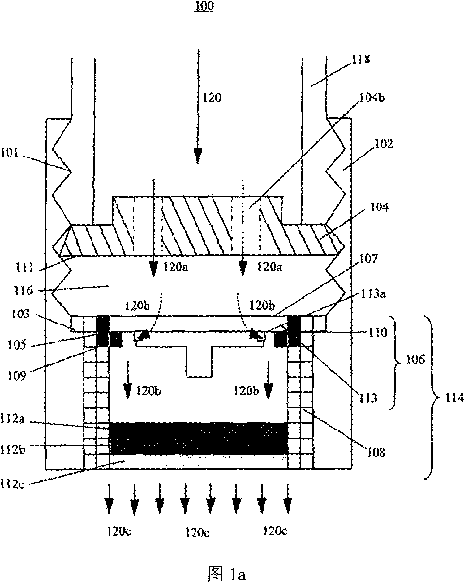
[0019] FIG. 1 a is a schematic diagram of a water saving device 100 according to an embodiment. The water saving device 100 includes a housing 102 , an upper flow control structure 104 , a lower flow control structure 106 and a mesh support 108 . In an embodiment, housing 102 is made of a material such as nichrome. There are threads 101 on the inner peripheral surface of the shell 102 . The thread 101 starts from the upper end of the housing 102 and extends to about half of the height of the housing 102 . A washer 103 within the housing 102 is located near the end of the thread 101 . The lower flow control structure 106 consists of a disc 113 and an annular body 110 .

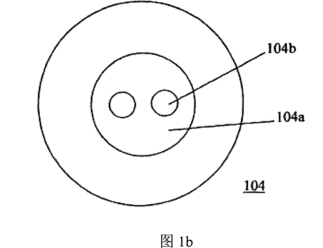
[0020] Figure 1b is a plan view of the upper flow control structure 104 in one embodiment. The upper flow structure 104 has a circular protrusion 104a in the center. Two circular holes 104b are arranged on the centerline of the surface of the protruding portion 104a. Two circular holes 104b extend from th...


PUM


Abstract

A water saving device(100)for use at or near a water outlet comprises a first water flow control element(104); a second water flow control element(106)disposed downstream of the first control element; a chamber(116)formed between the first and second control elements; wherein all of one or more water flow control parts of the second control element are made from substantially solid material.

Description

technical field [0001] The present invention relates broadly to water saving devices for use at or near water outlets. Background technique [0002] Previously, fresh water was freely available and considered by some to be an inexhaustible resource. Many places provide commercial consumers as well as residents with unlimited water at very low prices. In this way, water conservation is hardly a priority, and almost no one considers the design of water-using equipment. [0003] A combination of growing urban populations and low and near-drying water tables around the world is reducing the amount of fresh water available to the public. Faced with these problems, people began to realize the need for water-saving devices, and in some cases even urgently need water-saving devices. In view of this, tap water charges are implemented in many parts of the world. [0004] Due to current water conservation efforts, housewives and business managers are actively seeking ways to save w...

Claims


Application Information

Patent Timeline
IPC IPC(8): E03B7/07E03B7/09E03C1/02E03C1/08
CPCE03C1/08E03C2001/026
Inventor 龙猛
Owner JVL ENG PTE
Why Eureka
Try Eureka