Double wheel normal rotor engine

A rotary engine, engine technology, applied in combustion engines, machines/engines, internal combustion piston engines, etc., can solve problems such as energy consumption, increased wear, and unfavorable rapid and comprehensive combustion of gas

A rotary engine, engine technology, applied in combustion engines, machines/engines, internal combustion piston engines, etc., can solve problems such as energy consumption, increased wear, and unfavorable rapid and comprehensive combustion of gas

CN1944983AInactive Publication Date: 2007-04-11张志远

Image

  • Double wheel normal rotor engine
  • Double wheel normal rotor engine
  • Double wheel normal rotor engine

Examples


Embodiment Construction

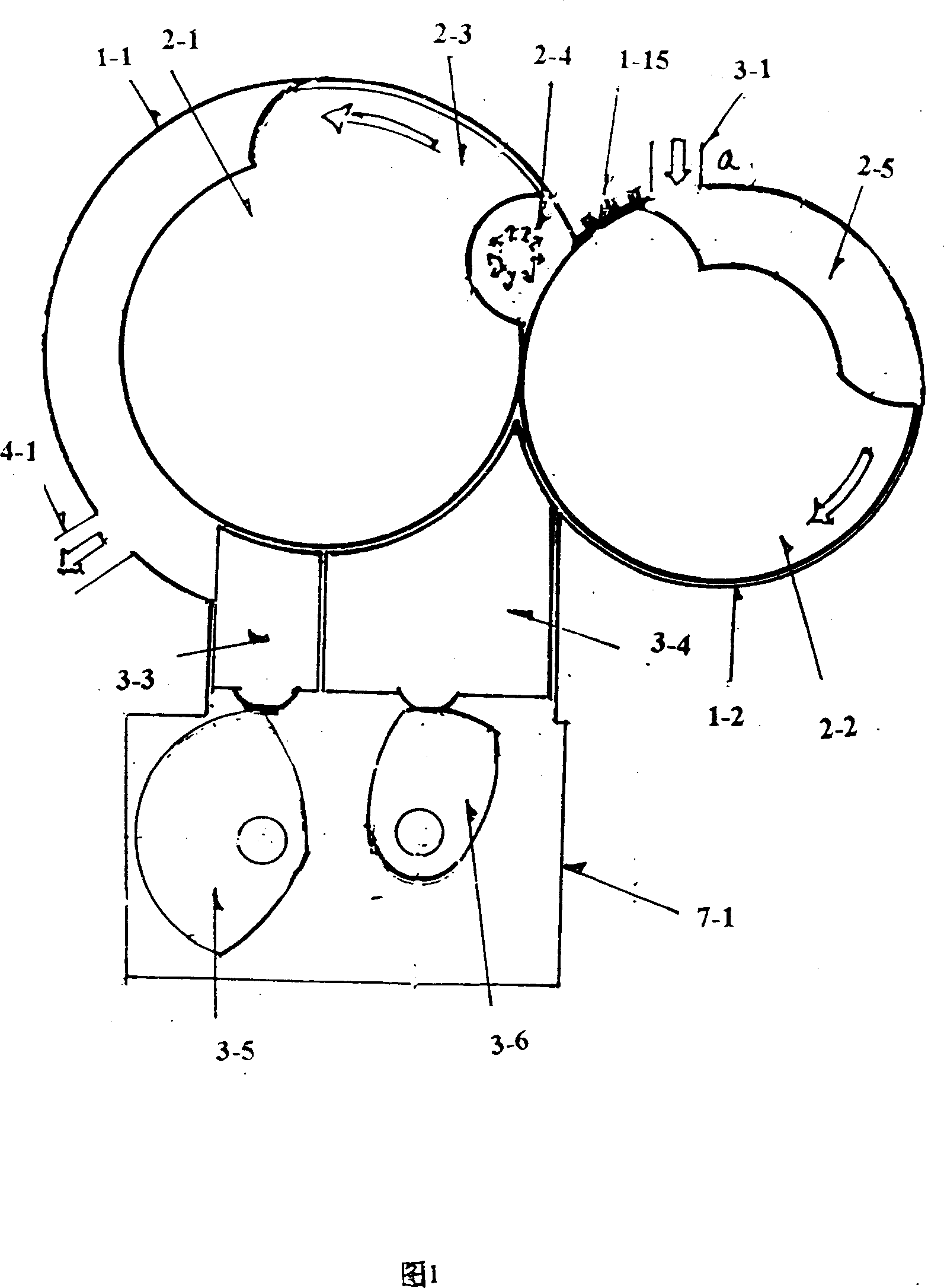
[0044] As shown in Figure 1: This is a structural schematic diagram of the first segment of the working principle of the engine. Wherein, some components are the same as those of the prior art, and some components need to be further described in the accompanying drawings. The first stage of the working principle of this engine is combustion explosion, when the main wheel 2-3 above the main wheel 2-1 rotates to the upper position, the fresh air in the compression chamber 2-4 has been compressed, and it acts as a combustion chamber The beginning part is ignited by the spark plug. Since the shape of the combustion chamber is close to a cylinder, the way the fresh air inside is pressed in is to generate a swirl flow along the cylinder space, which creates good conditions for the propagation and dispersion of the combustion flame. The condition of the compression chamber in the prior art, especially the shape condition of the compression chamber of the triangular rotor engine which...


PUM


Abstract

The double wheel rotor engine includes one case comprising cylinder body and cover; one main motion system with most parts in the cylinder and shaft extending beyond the cylinder; one gas distributing system comprising air strainer, total gas inlet pipe, turbocharger and other parts; one water or air cooling system; one lubricating system comprising lubricant tank, oil pipes, filtering and cooling supercharger, driving gear and lubricated parts; and one igniting system with power source, electronic igniting controller and spark plug. The present invention produces rotation power directly with the double wheel rotor engine, which has small size, light weight, great output power, low noise and easy cooling and is suitable for automobile, ship, small airplane, etc.

Description

Technical field: [0001] The invention relates to an engine, in particular to an engine with outstanding energy-saving effect, small size, light weight, high horsepower, low noise and low vibration, which can be widely used in automobiles, ships, motorcycles and various rotors with fuel as the power source. engine. Background technique: [0002] Since the advent of the internal combustion engine in the 18th century, human beings have entered the era of machinery replacing human labor. Engines are widely used in various mechanical powers, especially the power of transportation machinery, which greatly promotes the development of productivity and human progress. An industrial revolution. In nearly three hundred places, the contribution of the engine in liberating the labor force and promoting the development of productivity is huge, but its basic configuration and structural design, like other science and technology, have the characteristics of the dynasty and are not perfect....

Claims


Application Information

Patent Timeline
11 Apr 2007
Publication
CN1944983A
IPC
F02B53/02
CPC
Y02T10/17; Y02T10/12
Inventors
张志远; 张昊