Household gas leakage safety valve

A technology of gas leakage and safety valve, applied in the direction of valve lift, valve details, valve device, etc., can solve the problems of insufficient service life and insufficient sealing performance, and achieve the effect of good sealing performance and long service life

Inactive Publication Date: 2007-04-11
陈先仁
View PDF1 Cites 12 Cited by
  • Summary
  • Abstract
  • Description
  • Claims
  • Application Information

AI Technical Summary

Problems solved by technology

The seals of the self-closing valves in the two patent documents are subject to friction and may be in contac

Method used


Image

  • Household gas leakage safety valve

Examples


Example Embodiment

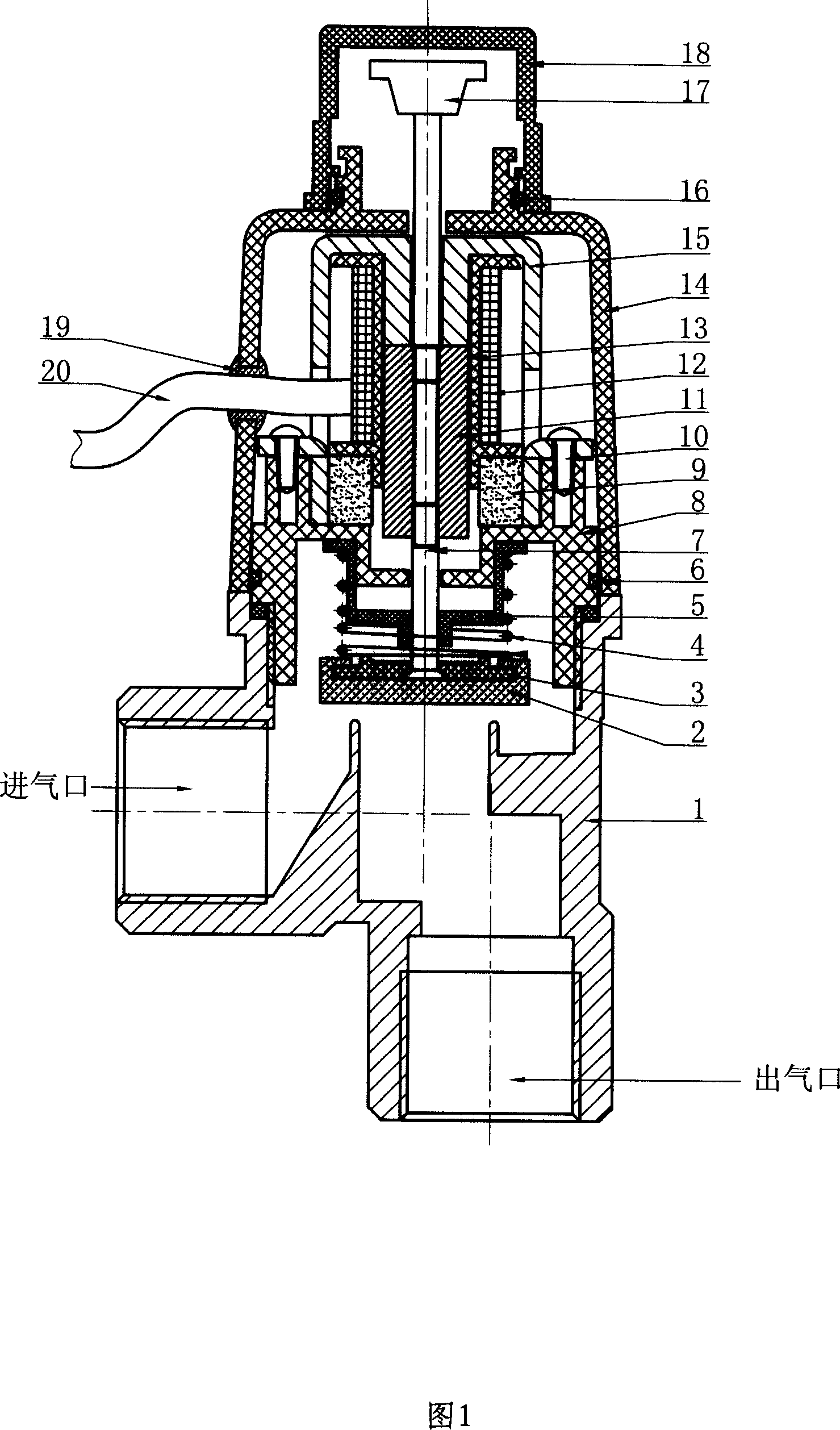
[0009] As shown in Figure 1, the household gas leakage safety valve consists of a valve body 1, a fixed frame 8 threaded with the valve body 1, a valve cover 14 sleeved on the fixed frame 8, and a self-tapping screw 10 mounted on the fixed frame 8. The coil support 15 on the top, the coil support 13 that is contained in the coil support 15, the coil 12 that is contained in the coil support 13, is contained in the magnet 9 between the fixed support 8, the coil support 15 and the coil support 13, is contained in the coil support The spool 11 in 13 forms. The upper and lower parts of the spool 11 are equipped with an upper pull rod 17 and a lower rod 7 respectively, the bottom of the lower rod 7 is equipped with a gasket 3 and a seal 2, and the outer surface of the lower rod 7 is equipped with a sealing sleeve 5 and a spring 4. The coil 12 is connected with the wire 20, and the place where the wire 20 passes through the valve cover 14 is protected by a wire buckle 19.

[0010] A...


PUM


Abstract

The present invention relates to valve, and is especially household gas safety valve with pull-push device for locking and cutting off without accident action. The household gas safety valve consists of valve body, fixing frame, valve cover, coil holder, coil, magnet and valve core. It has also upper pull rod in the upper part of the valve core, lower pull rod in the lower part of the valve core, pad and sealing piece below the lower pull rod, and sealing jacket and spring outside the lower pull rod. The present invention has features of high sealing performance, long service life, etc.

Description

Technical field [0001] This invention relates to valves, and more particularly to devices that lock or release by pushing or pulling to prevent accidental operation. Background technique [0002] At present, the domestic gas leakage safety valve that is locked or disconnected by pushing or pulling to prevent accidental action, such as CN03271972 "Automatic Safety Control Instrument for Coal Gas and Liquefied Gas Leakage", consists of two parts: a gas leakage detector and an automatic closing valve; The self-closing valve includes a valve, a valve core, a mechanical transmission mechanism and an electromagnet. There is also 200520107976 "Automatic Safety Control Instrument for Natural Gas Leakage", which is also composed of two parts: a gas leakage detector and an automatic closing valve mechanism; wherein the automatic closing valve mechanism includes a valve, a valve core and an electromechanical transmission mechanism. The seals of the self-closing valves in the two paten...

Claims


Application Information

Patent Timeline
IPC IPC(8): F16K1/00F16K31/06
Inventor 陈先仁
Owner 陈先仁
Why Eureka
Try Eureka