Control system and device

A control device and control system technology, applied in general control systems, control/regulation systems, computer control, etc., can solve the problems of complicated hardware structure and control programs, achieve simple structure, and increase the effect of input and output devices

Active Publication Date: 2007-04-11
HITACHI LTD
View PDF1 Cites 5 Cited by
  • Summary
  • Abstract
  • Description
  • Claims
  • Application Information

AI Technical Summary

Problems solved by technology

[0004]However, the technology of Patent Document 1 requires multi-drop connection by one cable, so a bidirectional serial transmission line is used
Therefore, a three-state buffer is required, and the hardware structure and control program will become complicated

Method used


Image

  • Control system and device
  • Control system and device
  • Control system and device

Examples


no. 2 approach

[0057] Sometimes the received data cannot reach the serial receiver 30 due to disconnection of the serial transmission lines 300a, 300b, 300c, failure of other input and output devices, etc., and the output port 70 continues to maintain the output state when it is normal. In this case, it is assumed that the operation circuit connected to the output port does not operate in case of abnormality, and the alarm circuit can display an alarm.

[0058] Operations of the input / output devices 200a, 200b, and 200c of the second embodiment will be described with reference to the flowchart of FIG. 8 .

[0059] Since S51 , S52 , S54 to S60 in FIG. 8 are the same as S31 , S32 , S34 to S40 in FIG. 5 , the description will be omitted, and S53 , S62 , and S64 will be described.

[0060] In S53, it is determined whether there is received data. If there is received data, the CPU 10 makes a determination of "Yes", and proceeds to S54. On the other hand, if there is no received data, the determ...

no. 3 approach

[0064] In each of the above-described embodiments, primary-line reciprocating electric wires are used as the serial transmission lines 300a, 300b, and 300c, but optical fibers may also be used as the serial transmission lines.

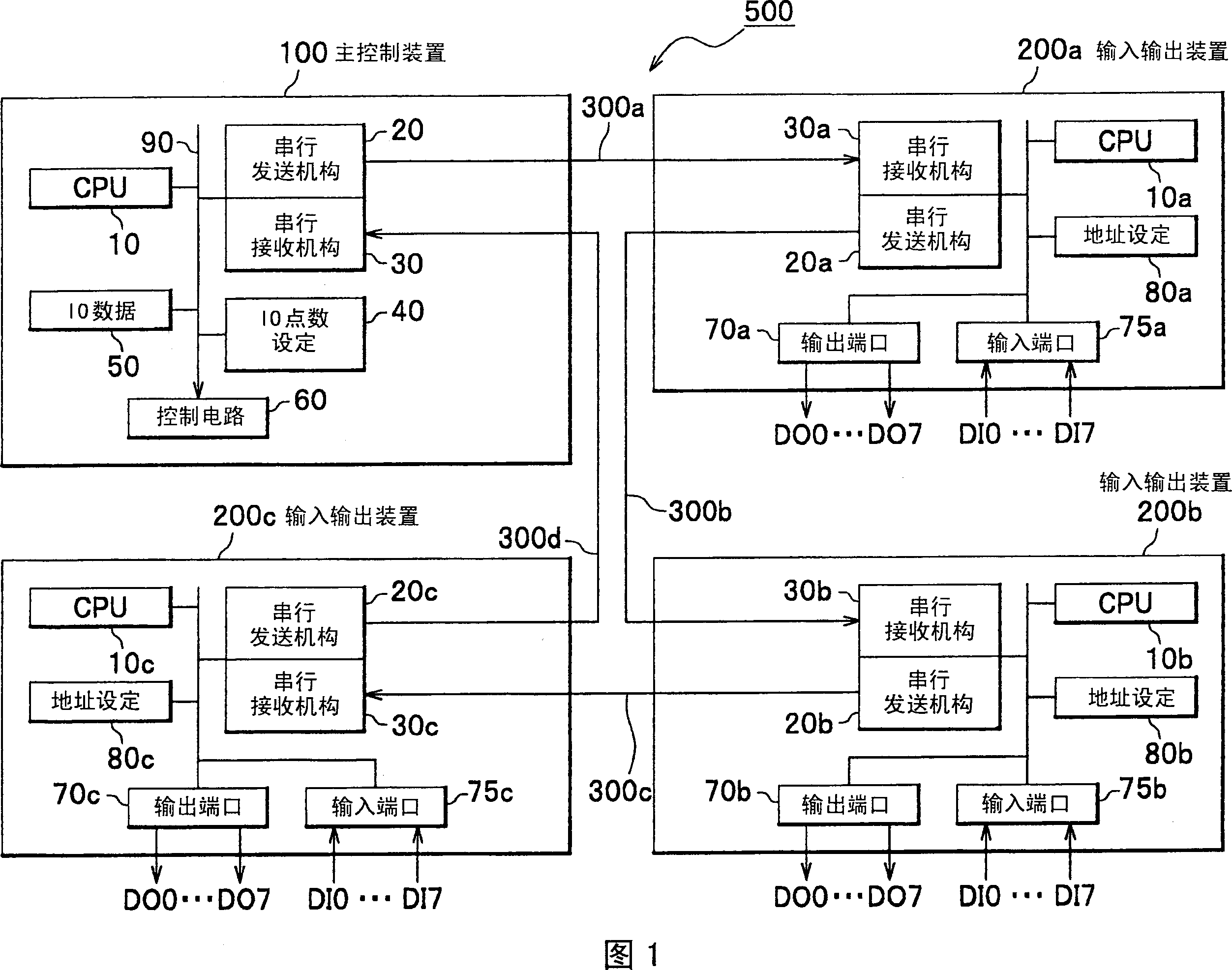
[0065] Referring to FIG. 9 , the configuration of the control device 520 according to this embodiment will be described. In FIG. 9 , the same reference numerals as those in FIG. 1 are attached, and the description thereof will be omitted. The difference from FIG. 1 is that an E / O converter 25 for converting an electrical signal into an optical signal, an O / E converter 35 for converting an optical signal into an electrical signal, serial transmission lines 300a, 300b, 300c, 300d is changed to optical fibers 350a, 350b, 350c, 350d, and connects the main control device 120 and the input / output devices 220a, 220b, 220c. In addition, in this embodiment, since the serial transmission is only performed in one direction, even if the optical fibers 350a, 350b,...


PUM


Abstract

A control system is provided with a first serial transmission line 300a for uni-directionally transmitting monitoring information for monitoring external equipment from a main controller 100 to input / output devices 200a, 200b and 200c in the order of the designation of input / output ports 70a to 75c, and a second serial transmission path 300d for uni-directionally transmitting control information for controlling the external equipment from the input / output devices to the main controller in the order of the designation of the input / output ports. Furthermore, the main controller 100 and the plurality of input / output devices are annularly connected through one or more third serial transmission paths 300b and 300c for connecting the plurality of input / output devices 200a, 200b and 200c and the first serial transmission line and the second serial transmission line. Thereby, the invention increases the input / output device with simple configurations.

Description

technical field [0001] The invention relates to a control system and a control device for performing remote monitoring and control on external equipment. Background technique [0002] In a large-scale control device such as a device control device, a processing device called an auxiliary device is generally used, and in order to improve the controllability and reliability of the processing device, control and protection functions on the operation side are often added. Along with this, the number of input and output points of the controller increases and the number of wirings increases. In order to avoid this problem, a technique is disclosed in which a main control device and a plurality of input / output devices are connected in series by a multi-drop (daisy chain) to perform remote control (Patent Document 1). In addition, the same document also describes that a serial signal is transmitted asynchronously using a single cable. [0003] Furthermore, in the exhaust system, a...

Claims


Application Information

Patent Timeline
IPC IPC(8): G08C19/16G05B19/02G05B15/02
Inventor 松田敏彦川原吹和男执行正谦
Owner HITACHI LTD
Why Eureka
Try Eureka